Testing Directional Overcurrent Relays
In the previous post about Directional Overcurrent relay (67) testing (Finding the Direction in Directional Overcurrent Relays), we reviewed Directional Overcurrent protection from a system perspective to enhance the descriptions in The Relay Testing Handbook: Principles and Practice. We’ll be looking at Directional Overcurrent relays from a testing perspective in this post.
Successful Directional Overcurrent tests have three parts:
- Your current must be above the pickup setting.
- Your current must be in the correct direction.
- You must have a polarizing signal.
A traditional relay tester, or automated testing software, will often apply a test scenario like the following:
| Channel | Magnitude | Angle | Instruction |
| Ia | > Pickup setting | 0° (default) | Raise until pickup |
This test plan may work depending on the sophistication of the relay, but there’s a pretty good chance that the pickup tests will work, and the timing test will fail. In this scenario, you might get frustrated and start disabling the directional function, or start looking for the non-directional relay definitions so you can map them to a test output. Let’s take a closer look at your test plan before you, or your test software, head down that path.
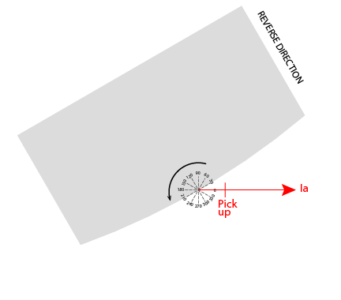
Based on the drawing of your test plan, it looks like you’ve met the first two criteria for a successful Directional Overcurrent test:
- The current is greater than the pickup setting.
- The current is in the tripping direction. (Not in the shaded area)
But do you have a polarizing signal?
Testing Directional Overcurrent Relays That Use Phase-to-Phase References
Imagine that I asked you for directions to your favorite restaurant after dark. You could give me directions like, “If you head north for ten blocks and then east for three blocks, you’ll find the best BBQ in the county.” Your directions are perfect, but I’ll be hungry until I find a compass or someone to give me a reference like, “North is that way”. However, if you said, “Turn right for ten blocks and then turn right for three more blocks”, I’ll be eating the best BBQ in no time.
Directional relays need a reference to work correctly, and that reference is called the polarizing signal. The Directional Overcurrent element needs a polarizing signal to operate reliably; otherwise anything could happen depending of the sophistication of the relay.
Most electro-mechanical relays, and GE relays like the one from The Relay Testing Handbook example, use the phase-phase voltage from the two un-faulted phases as a polarizing signal. You could drive yourself crazy trying to figure out how to apply the test and phasor diagrams from older relay manuals to modern test-sets.
Or you can test all relays that use the un-faulted voltages as a polarizing signal by simply applying three-phase balanced voltages as shown in this phasor diagram from the previous post. We added the B-C phase-phase voltage to the drawing, which is the polarizing voltage this style of relay uses.
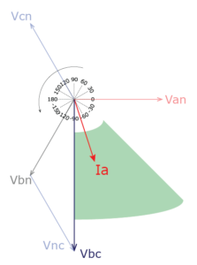
If we rotate the standard phasor diagram by 90° and add the same labeling used by the relay bulletin drawings, we can see that simply adding voltage will allow us to successfully test every relay of this type.
| Channel | Magnitude | Angle | Instruction |
| Ia | > Pickup setting | 0° (default) | Raise until pickup |
| Va | Nominal V | 0° | |
| Vb | Nominal V | -120° | |
| Vc | Nominal V | 120° |
Testing Directional Overcurrent Relays That Use Negative Sequence References
Unfortunately, not every relay uses phase-phase voltages as a polarizing signal. Some relays use the negative sequence voltage as the polarizing signal. Negative sequence voltage can be simplified to mean unbalanced voltage (You can get more information in the Sequence Components section of The Relay Testing Handbook: Principles and Practice). Are the voltages unbalanced in the previous test plan?
You can tell by graphically adding the three voltages together, or with the negative sequence formula.
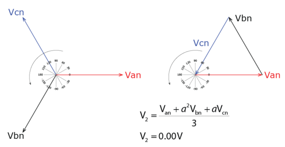
The negative sequence, or unbalance voltage, is zero in a balanced system. Therefore, our previous test plan will not have a polarizing signal on relays that use negative sequence polarizing.
We can fix this problem by thinking about what happens during a phase-to-ground fault.
- What happens to the faulted voltage? The faulted voltage will drop; how much it drops depends on the severity of the fault. The worst possible fault would drop the fault voltage to near zero, but most faults won’t be that severe. We can cut the faulted voltage in half to simulate a phase-to-ground fault.
- What happens to the faulted current? The faulted currents will jump to a higher value, and we know from the relay settings how much current we need for the relay to detect a fault. Set the fault current at least 110% of the relay’s pickup setting.
- What happens to the other voltages and currents that aren’t faulted? They would change slightly during a real fault, but you would need some modelling software to figure out how much. We can assume that they don’t move, like textbooks do, for testing purposes.
If we alter our test plan to better simulate a fault, it would look like the revised plan below.
| Channel | Magnitude | Angle | Instruction |
| Ia | > Pickup setting | 0° (default) | Raise until pickup |
| Va | One-half V | 0° | |
| Vb | Nominal V | -120° | |
| Vc | Nominal V | 120° |
A plan to Test any Directional Overcurrent Relay
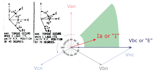
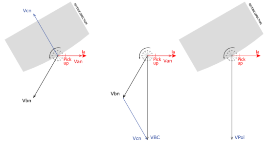
Now our Directional Overcurrent (67) test plan looks like the following drawing where we start with the raw currents and voltages, calculate the non-faulted phase-to-phase voltage, and plot the operating current and polarizing signal, which in this case is VBC. This test plan has a good chance of being successful because we have an operating signal and a polarizing signal.
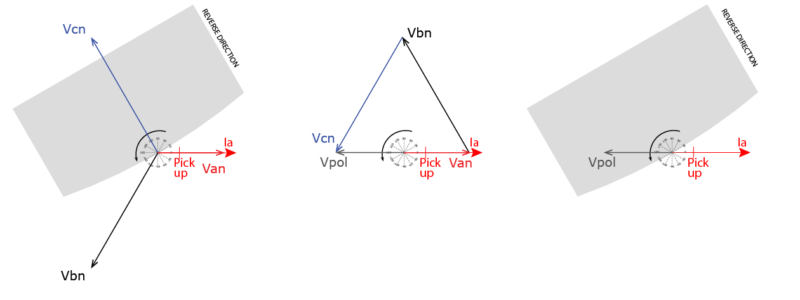
These drawings look at the same test plan for a Directional Overcurrent (67) element that uses negative sequence voltage. We start with the raw currents and voltages, then calculate the negative sequence voltage, and then plot the operating current and polarizing signal (V2). This test plan has a good chance of being successful because we have an operating signal and a polarizing signal.
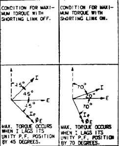
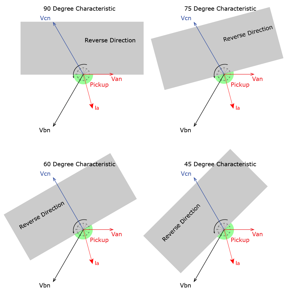
We appear to be in good shape for most Directional Overcurrent (67) applications. However, there will be times when this test plan will not work. What are the odds that a phase-to-ground fault will be 100% resistive? The answer is never. Actually, there are almost no purely resistive systems as we discussed in the previous article, so our test current at zero degrees can cause problems, especially near generation systems like wind farms that can have crazy characteristics or very high voltage (>115kV) applications. Some relays have an operating characteristic like the following picture:
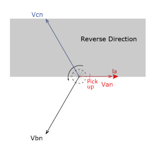
Notice that our test current is right on the edge of the reverse direction. This means that it is a coin toss whether the relay will operate or not. We can ensure the relay always operates by setting the faulted current to a fault angle that would happen in the system. You can choose a good fault angle using one of these methods:
- Most modern relays have a positive sequence angle setting that defines the expected fault angle. Set the fault angle to that setting.
- If you have a good understanding of fault characteristics, you could guess the fault angles.
- A very high voltage system (>115kV) will have a characteristic near 90 degrees, so you could safely choose a fault angle of 87°.
- A high voltage system (>69kV) will have a fault angle closer to 75°.
- A distribution system (>34kv) will have a fault angle closer to 60°.
- A medium voltage system will have a fault angle closer to 45°.
- You can never go wrong with a fault angle of 60° or 75°. This is what electro-mechanical relays used because their options were limited and they needed a good average.
Our test will work for all common characteristic angles if we modify it to include the phase angle during a fault.
| Channel | Magnitude | Angle | Instruction |
| Ia | > Pickup setting | 75° (or fault angle) | Raise until pickup |
| Va | One-half V | 0° | |
| Vb | Nominal V | -120° | |
| Vc | Nominal V | 120° |
Directional Overcurrent Relay Test Plan Summary
Testing Directional Overcurrent (67) elements is almost as simple as testing standard Overcurrent (50/51) elements as long as you properly simulate a fault. I used to occasionally run into problems when testing Directional Overcurrent (67) elements using traditional testing techniques. I would spend a lot of unnecessary time trying to figure what went wrong as I said to myself, “I know I’m doing it right, why won’t this relay work right!!!” Now I always follow these steps before running any test:
- Connect all currents and voltages
- Choose the fault type to apply
- Apply nominal balanced three-phase voltages
- Cut the fault voltage in half
- Raise the fault current more than 110% of the pickup setting
- Make sure the fault current lags the fault voltage by the fault angle or 75°
Modern testing equipment makes this easy, which means you can spend more time understanding the application so you can become a true relay testing craftsman.
Please like and share this post if you found it useful. It helps us get noticed, which means we can post more free content.
Add your comments for Directional Overcurrent relay (67) testing in the comments section, start a new topic by becoming a TechTalk Contributor, or you can ask me questions about other topics with the Ask Chris form.
Happy Testing!
Discover more from Valence Electrical Training Services
Subscribe to get the latest posts sent to your email.
Did you like this post?
You can share it with these links:
Read More Articles:
NETA Continuing Technical Development Credits (CTDs)
Very useful information.
Thanks
One think I still don’t understand is why is the reverse direction not defined when the current Ia laggs the voltage Van by more than 90Deg. This would correspond to a 0 Deg Characteristic.
The current can’t lag the voltage by more than 90 degrees as described in the previous post. A current in that quadrant is either a better than perfect inductor, or a reverse capacitor.
If it lags by more than 90 (i.e. a 0 Degree Characteristic) , it implies there is a negative resistive component, or put differently, power is flowing in the opposite direction. It is thus a reverse fault. This is for me where the boundary should be. If on the other hand a 90 Degree Characteristic is chosen, and a “capacitive” cable has a fault, the leading current would look like a reverse fault.
Read the two posts again and pay particular attention to the figures.
A forward current that lagged by 91 degrees lag would have negative resistance and more inductance than a perfect inductor. Impossible!
If a reverse current lagged by 91 degrees, that would be nearly 100% capacitive current flowing in the opposite direction. Why would a relay care about that unless an out-of-step was in progress?
Hi Chris,
Many thanks , very interesting explanation .
Thanks
Thanks for the kind words.
Hello Sir,
So, Is there any method to generate phase shift and vary it smoothly for testing of directional overcurrent relay using equipments available in the laboratory.For colleges which do not require accuracy and which does not have enough capital to afford a high-end testing equipment, this would be very helpful.Kindly help.
Not that I know of. We had to use signal generators back in the day, but you also need a phase angle meter and constantly vary the frequency. ISA test sets are usually inexpensive compared to other test-sets. You might try them.
Hi Chris,
How can I find or set the threshold polarization values of voltage and current for the diferrent methods, like zero sequence polarizing or negative sequence polarizing?
Thanks
Different relays have different settings for those settings. You can usually find them in the directional settings. Some relays like SEL, for example, use dynamic directional elements and use impedance blinders instead.
But, How can I calculate those values properly?
You would have to talk to your engineering department and relay manufacturer. It is called the art and science of protective relaying for a reason.
This post has given me insight in testing directional relays. Thank you verymuch.
Thanks for the kind words.
usually, we have an MV generating system of 6.6KV and we are going to synchro with the grid. to avoid a reverse power to the grid? what is the right value we should set in our relay, note that the protection relay type, SEPAM series 80
That’s a question for an engineer who has all the information for your site and can make an informed decision.
good information
Thanks for sending all videos or papers
Thank you very much for the explanation.
I am very grateful.
Awesome explanation on testing 67 elements. Thank you!
عالی بود
Excellent
Hi Chris
Two questions about ISA test software.
The first question:
What does what mean star point vt?
Second question:
In the directional earth fault test in ISA tester, when the reference is residual voltage (-Vres) in at the tip of the reference voltage arrow why The performance area shows the residual voltage (+Vres)as a reference according to the current and voltage injected to the relay
I’ve only used the ISA software once, so I would have to see pictures to make sense of your questions.
Are you sure you don’t mean star point CT?