Use Sequence Components To Make Sure Your Relay Isn’t Disabled By Incorrect Phase Rotation
Did you know that a relay connected to, or set with, the incorrect phase rotation can disable its higher level functions? Did you know that the wrong phase rotation can make your relay testing worthless? Did you know you can quickly and easily tell whether the phase rotation is correct using sequence components without the complex calculations usually involved with sequence components?
You can successfully test relay elements that use directional control (directional overcurrent (67) or impedance (21), for example) under ideal test conditions. However, those elements will NOT operate if the power system’s phase rotation doesn’t match the relay settings. This means that you should make sure the phase rotation is correct when performing your online and offline meter tests.
You should understand all the background information we covered in the following posts before you read further:
- Drawing Phasor Diagrams for Relay Testers (https://relaytraining.com/drawing-phasor-diagrams-for-relay-testers/?highlight=phase%20angle)
- How to Measure Phase Angles with a Phase Angle Meter (https://relaytraining.com/measure-phase-angles-phase-angle-meter/?highlight=phase%20angles)
- How to Understand and Determine Phase Rotation in a Power System (https://relaytraining.com/understand-determine-phase-rotation/?highlight=phase%20angles)
- How to Perform an In-Service Protective Relay Meter Test (https://relaytraining.com/perform-service-protective-relay-meter-test/?highlight=phase%20angles)
The following chart includes the values generated for a three-phase balanced offline-meter test into an SEL-351 relay using a Megger Test-Set or RTS.
|
Test-Set |
Relay | Magnitude | Angle |
| Voltage Channel V1 | VA | 69.28V | 0° |
| Voltage Channel V2 | VB | 69.28V | 120° |
| Voltage Channel V3 | VC | 69.28V | 240° |
| Current Channel I1 | IA | 1.000A | 0° |
| Current Channel I2 | IB | 1.000A | 120° |
| Current Channel I3 | IC | 1.000A |
240° |
The relay is connected to 300:5 CTs and 35:1 PTs. Is everything correct in the following meter test?

Here’s what we know so far:
- The metering results aren’t zero, which means the relay’s analog to digital converters are working.
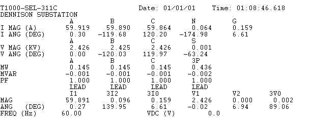
- The CT and PT ratio settings in the relay are correct (notice that we don’t need to look at the actual settings to determine this). We’re injecting 1A in all three phases and the relay is reporting approximately 60A. The worst-case accuracy is -0.355% error, which is consistent with the 60:1 CT ratio. The relay is reporting approximately 2.42kV in all three-phases with a maximum percent error of -.07%, which matches the PT ratio.
- The relay is looking in the correct direction because the currents and voltages are in-phase.
- We are injecting A-B-C, or 1-2-3, rotation because the following pattern exists in the relay and test-set: A-Phase is 0°, B-Phase lags A-Phase by 120°, and C-Phase lags A-Phase by 240°.
- The relay is programmed with the WRONG phase rotation because the sequence components show 0% positive sequence, 100% negative sequence, and 0% zero-sequence.
Looking at the phase angles on the metering report will not tell you if the phase rotation is correct. Looking at watts does not tell you that the phase sequence is correct on a modern digital relay (it used to be a good test in the 90s, but no longer). You have to understand some simple principles of sequence components to verify the relay is connected to, and programmed to look for, the correct phase rotation.
You probably want to start running for the hills right now because if you’ve ever sat through a lesson on sequence components, it might have been the most confusing (or boring) concept you’ve ever seen and wondered why it applies to you. I promise that you do NOT need to perform sequence component math to understand some basic principles that will make you a better relay tester.
Basic Sequence Component Principles
Sequence components can be difficult to understand because they were created by a mathematician around 1918 to “simplify” fault analysis for engineers. A typical sequence component lesson includes complex math, phase rotation operators, and equivalent circuits to calculate the three sequence components that CANNOT be measured. Instructors and textbooks typically use terms like:
- Positive-Sequence Components rotate in the positive phase sequence.
- Negative-Sequence components rotate in the reverse phase sequence.
- Zero-Sequence Components do not rotate.
You can read the Sequence Components section of The Relay Testing Handbook: Principles and Practice to learn the basic sequence component math involved, or read any electrical engineering textbook to dig deeper. We only need to understand some basic rules to use sequence components in our meter tests.
100% Positive-Sequence can only occur if these three statements about the power system are true:
- The voltage/current/impedance magnitudes for all three phases are equal.
- The three phases are 120° apart.
- The phase sequence is correct.
100% Negative-Sequence can only occur if these three statements about the power system are true:
- The voltage/current/impedance magnitudes for all three phases are equal.
- The three phases are 120° apart.
- The phase sequence is reverse.
The Zero-Sequence will always be zero unless the system is unbalanced by a ground fault or single-phase problem.
Looking for Sequence Components on a Metering Report
Phase descriptions are usually something like A-B-C, R-S-T, or 1-2-3. Sequence components use the 1-2-0 symbols after the unit they represent. If you look near the bottom of the metering report, you can see the symbols:
- I1 = Positive Sequence Current
- 3I2 = Negative Sequence Current multiplied by three = 3xI2 = I2x3
- 3I0 = Zero Sequence Current multiplied by three = 3xI0 = I0x3
- V1 = Positive Sequence Voltage
- V2 = Negative Sequence Voltage
- 3V0 = Zero Sequence Voltage multiplied by three = 3xI0 = I0x3
Troubleshooting Phase Rotation during Meter Tests
Now that you know the symbols and patterns to look for, you can see that I1 and V1 are essentially zero. I immediately know something is wrong when I see this pattern, because a three-phase balanced system in the correct phase rotation should create 100% Positive Sequence. Zero positive sequence can only really happen in a properly configured system if the phase magnitudes were also zero.
The Zero Sequence components (3I0 and 3V0) are essentially zero and are created by the slight, but inherent, test-set and relay inaccuracies used during the test (Nothing is perfect, even though relay testers are often looking for perfection in their results). This is usually a good sign because you should only see significant Zero-Sequence components during ground faults or single-phase problems.
The Negative Sequence components (3I2 and V2) equal 100% of the injected per-phase voltages (2.424kV) and currents (179.593 / 3 = 59.86A). This pattern can only exist if one of the following is true:
- Your test-set is injecting the wrong phase sequence during your test
- Two phases are swapped between the source (test-set or power system) and relay
- The power system has the wrong phase sequence
- The relay is programmed with the wrong phase sequence
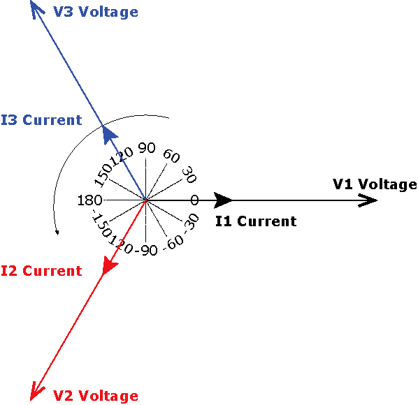
In this case, we would look at the test-set phasor diagram to make sure that the test-set is exporting the correct phase rotation. Notice that I didn’t tell you to look at the phase angle numbers. It’s hard to keep track of angle systems when you use test-sets and software that use different phase angle systems. Phasor diagrams are universal. The following phase angle diagram from the test-set shows A-B-C rotation.
The relay is measuring the correct phase rotation, so the wiring between the test-set and relay probably isn’t crossed.
We can’t tell if the relay setting matches the power system until we perform an in-service meter test. We can compare the phase sequence on the drawings to our test-set phasor diagram to make sure we are matching the expected phase rotation of the system.
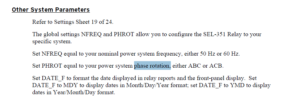
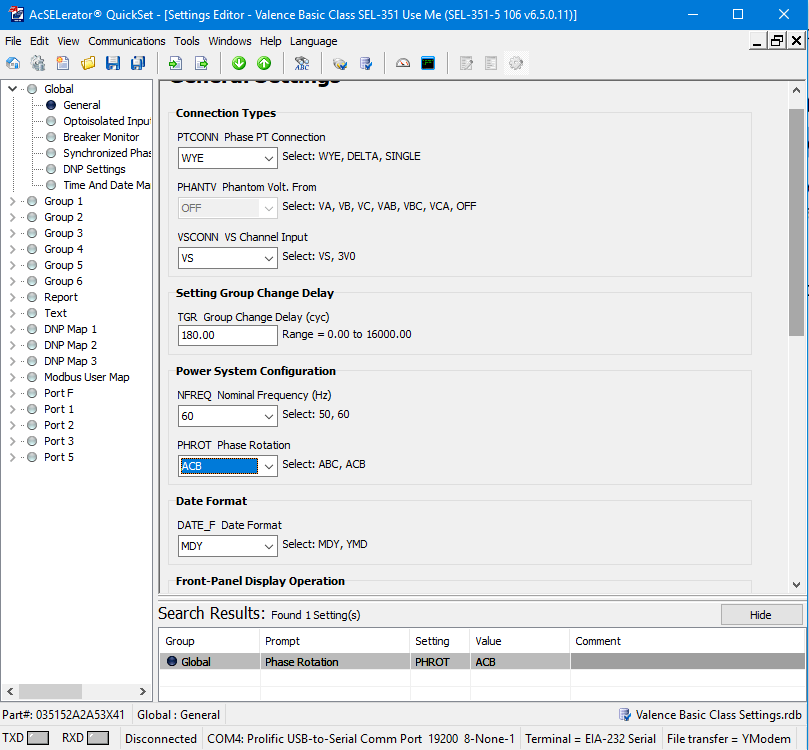
The only other option left is the relay setting. We can search the manual for “phase rotation” or “phase sequence” to find the correct setting. The correct setting is PHROT in the Global settings group of an SEL relay, as per the manual screenshot below.
If we search the relay settings for PHROT, we will find out that it is set to ACB, which does not match the specified ABC rotation.
Now that we know what the problem is, we can contact the design engineer to point out the problem. Your email might include something like: “We found that the applied relay setting PHROT = ACB. The site drawings indicate that the actual system rotation is ABC. Should this setting be ABC? Please supply updated settings, or provide authorization to change the setting to ABC, if applicable.”
If the setting change is approved, we can change the setting to ABC and perform another meter test with the same values:
|
Test-Set |
Relay | Magnitude | Angle |
| Voltage Channel V1 | VA | 69.28V | 0° |
| Voltage Channel V2 | VB | 69.28V | 120° |
| Voltage Channel V3 | VC | 69.28V | 240° |
| Current Channel I1 | IA | 1.000A | 0° |
| Current Channel I2 | IB | 1.000A | 120° |
| Current Channel I3 | IC | 1.000A |
240° |
The pattern for this meter test is:
- V1 & VA & I1 & IA = 0 degrees, V2 & VB & I2 & IB = Lag A/1 by 120°, and V3 & VC & I3 & IC = Lag 1/A by 240°. The test-set is injecting ABC, and the relay is receiving ABC. The currents and voltages are in-phase.
- I1 & V1 = 100%, 3I2 & V2 = 0%, and 3I0 & 3V0 = 0%. The relay’s phase rotation is set correctly.
This is the pattern you should be looking for during every meter test.
Remember that in-service meter tests are just as important as all of your offline relay testing because the relay could be disabled if:
- The wiring or settings swap the phase rotation and disable the relay
- The relay is looking in the reverse direction because of design mistakes, wiring mistakes, or incorrect CT polarity. If the relay is looking in the wrong direction, the relay won’t operate when it is supposed to, and may operate when it’s not supposed to.
Sequence components can also tell you what’s wrong with your connections or test-set setup during testing. Make some intentional mistakes and see if you can find the pattern in sequence components to help you troubleshoot problems in the future.
Relays use sequence components to determine which kind of fault is occurring, and then apply the appropriate calculations for that fault type. Relay testers who try to apply electromechanical test procedures to digital relays often get the wrong sequence component patterns, which confuses the relay and prevents it from operating. Try applying P-N, P-P, and 3P faults into the relay and see if you can see the sequence component pattern for each kind of fault.
Discover more from Valence Electrical Training Services
Subscribe to get the latest posts sent to your email.
Did you like this post?
You can share it with these links:
Read More Articles:
How to Test Protective Relays Correctly
Dear sie,
I’m from INDIA, can you send me the concept of slope using in transformer.
We wrote several chapters about differential protection in The Relay Testing Handbook: Principles and Practice.
Great article and site.
I’m a retired testman, 3 1/2 years now.
Great profession for anyone who likes field work.
I believe that a typo exists at the end of your article though, believe you meant to say V3,&VC&I3 &IC =lag 1/A at 240 degrees.
Thanks
Thank you for the kind words.
You were correct about the typo and it has been corrected. Cut and paste is a terrible thing :)
This is a very interesting online learning resource for experienced and inexperienced engineers. How I wish this resource was available over twenty-six years ago when I was still in active service. A job well done!
Thanks for the kind words!