Finding the Direction in Directional Overcurrent Relays
A reader recently asked a question about the forward and reverse directions described in the Directional Overcurrent Relay section of The Relay Testing Handbook series. I used electro-mechanical directional relays as an example, which may have been a mistake. Let’s take another look at the Directional Overcurrent (67) element from a system perspective.
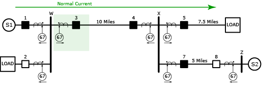
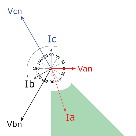
We will start with a simple transmission line with the source on the left and a load on the right. The current flows into the polarity mark of the CT on Breaker 3, and into the Directional Overcurrent (67) Relay using the same direction. Any current flowing into the polarity mark is considered to be the forward direction.
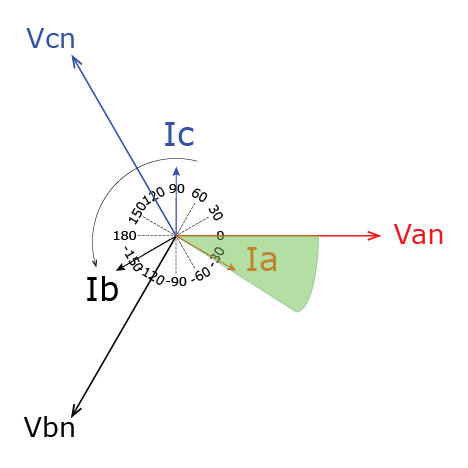
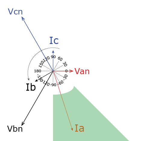
The phasor diagram for this situation might look like the following. Every load is a combination of resistance and inductance, so the normal operating range for this line is the green shaded region when the current flows into Circuit Breaker 3.
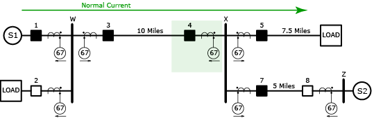
Let’s look at what the Directional Overcurrent (67) relay connected to Circuit Breaker 4 sees under the same conditions. This relay is designed to protect the same transmission line from the other direction. The current enters the non-polarity mark of the CT, and the relay determines that current is leaving the transmission line; or the reverse direction.
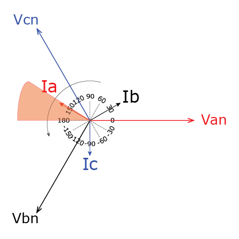
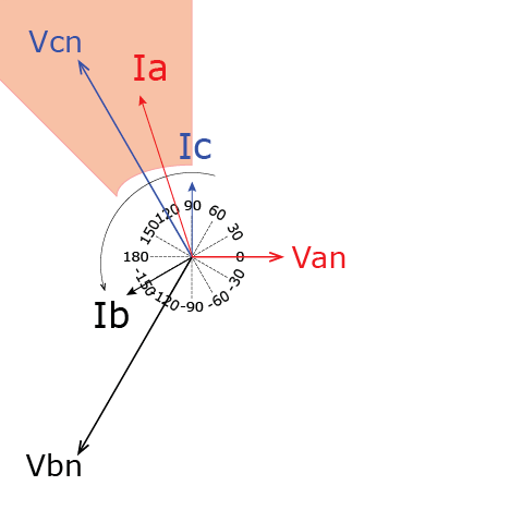
The phasor diagram of a meter test on the Directional Overcurrent (67) relay connected to Circuit Breaker 4 would look like the following. The current is flowing in the reverse direction and the orange/red shaded area displays the normal region when the current flows into a load behind the relay.
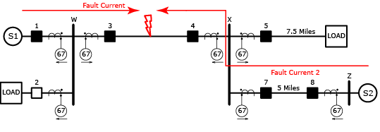
If we reversed the source and load, you could swap the phasor diagrams above for each relay. Let’s shake things up by closing Circuit Breaker 8 and applying a Phase A-to-Ground fault 50% down the line. This is a fault, so:
- The faulted voltage should drop in proportion to the severity of the fault
- The fault current should be significantly larger than the normal load current.
- The fault current should lag the voltage by 40-89.9 degrees depending on the line characteristics, voltage, and severity of the fault.
- The non-faulted phases should stay relatively the same.
Both fault currents flow into the transmission line, so the directional overcurrent relays connected to Circuit Breakers 3 and 4 will see the current in the forward direction because the current flows into both CT polarity marks.
If we pretend that the fault is exactly 50% down the line, both sources are identical, and the impedance between the sources and the fault are also identical, we can use the same phasor diagram for both relays. Obviously this won’t be true in the real world and the current magnitudes would be different. The typical region for a fault in the forward direction occurs in the green shaded area for both relays.
Now let’s look at a fault that is not on the transmission line.
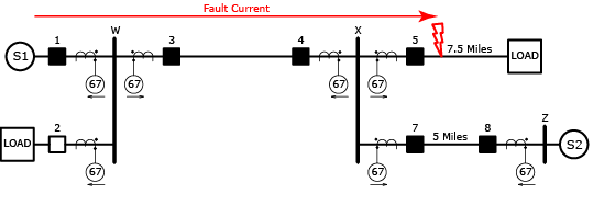
The fault current flows into the polarity mark of the CT connected to Circuit Breaker 3, so the Directional Overcurrent (67) relay sees the fault in the forward direction. If the fault current is larger than the overcurrent setting, the relay will trip.
Directional overcurrent protection schemes were replaced with line impedance relays (21) to prevent a situation like this from occurring. This relay’s primary purpose is to trip for faults on the transmission line, not for faults somewhere else on the system, as would happen here. A line impedance relay would recognize that the fault was not on the transmission line and ignore this fault unless it was programmed to also provide backup protection with a significant time delay.
The fault current flows into the non-polarity mark of the CT connected to Circuit Breaker 4, so the Directional Overcurrent (67) relay sees the fault in the reverse direction. The orange/red shaded region indicates the typical region for a fault behind a relay.
Overcurrent directional relays can be set to trip for faults in the forward direction, which will protect the equipment in front of the relay. Or they can also be set to trip for faults behind the relay in the reverse direction. Forward and reverse are typically determined by the normal flow of current into the relay, so be sure to confirm the CT connections before you make any assumptions.
Incorrectly determining forward and reverse is an easy mistake to make. If I ever have doubts about some relay settings or directional overcurrent tests, I usually ask the design engineer, “Did you mean to trip if the fault is on the transmission line, or on the buss?” (You can use whatever easy-to-define characteristic for your situation.) Once they answer that question, I will review the CT connections and build a test on the transmission line and see if it trips. I then apply the fault in the reverse direction to make sure it doesn’t trip. Always ask the engineer what they intended if there is any doubt.
You could also perform a test in either direction first and see what direction the relay is set to trip. If it doesn’t make sense to you, you can ask the engineer, “Did you mean for the relay to trip if there is a fault on the buss?”
I hope this helps clear up the definitions of forward and reverse for Directional Overcurrent (67) relays. The next post on this topic, “Testing Directional Overcurrent Relays“, will hopefully help clarify the characteristic angle.
Please share this article or leave a comment if you found it useful . It may not seem like much, but it helps us keep creating more free content for you.
Also, as a bonus you can click the image below to sign up and we’ll send you the free Finding Direction in Directional Overcurrent Relays Cheat Sheet. It distills what we just covered into a simple 2-page PDF summary you can print out and take with you:
Discover more from Valence Electrical Training Services
Subscribe to get the latest posts sent to your email.
Did you like this post?
You can share it with these links:
Read More Articles:
CT Primary Injection Ratio Testing Problems
Hi Chris,
Thank you for valuable articles for beginner like me.
I want your advice about setting directional overcurrent relay. On your SLD above what is the setting value of relay 67 for CB no 3 and 4?
Is it possible to have lower setting value (lower than normal current flow) of relay 67 for CB no 4?
This case happen during startup
Thank you
The pickup setting would always be set higher than the expected maximum current flow. Otherwise the relay would trip under normal conditions instead of fault conditions.
Some directional overcurrent applications have a pickup current set lower than the expected current, but these applications are designed to separate two systems when the current flows in an undesired direction.
For example, imagine a plant supplies all of its own electricity and keeps a feeder connected to the grid to use during emergencies ,and to sell excess power to the utility. Power from this utility is very expensive, so they never want to take power from the grid. They could set a directional relay with a low pickup setting that will only operate if power flows from the grid to the plant. Power from the plant to the grid will be ignored.
A lot of thanks
Very very good explanation. Easy to understand.
Thanks and keep it up!
Hello Chris,
I’m a beginner in this field and i am confused about Relay Operating Angle (ROA) and Relay Characteristic Angle (RCA) What is the difference between the two, could you please explain the use of each element?
Thank you in advance
Thanks for your question. Those terms could mean a variety of things. Can you send some context such as the source of these terms.
Hello,
My question refers to directional overcurrent protection function, in some relays we just put the angle setting for RCA and in other relay we should set both RCA and ROA. The question is what is the use of ROA settings.
Thanks for your question. Unfortunately, I am unfamiliar with an “ROA” setting and don’t know what it is.
Thanks for your explanation.
I have a question regarding reverse KVAR.
Will the 67 relay(Phase directional overcurrent) detect reverse current and trip the breaker if the capacitor bank power factor correction unit is feeding the utility with a substantial amount of KVAR due to the sudden decrease of the active load?
Some relays like GE UR relays allow you to define a specific direction with blinders, so those relays could be specified to look in any direction within a window. Other like SEL are looking for specific fault conditions, so they are less configurable in that way. Neither relay will properly determine VARs when using a 637 element. They can only apply current direction and magnitude. You would need to find a relay with a kVAR element to properly apply the protection you desire.
Hello,
In 67 function. Can anyone explain on what basis do we chose the right setting for Relay Characteristic Angle?
Thank you
From a relay testing perspective, you can approximate the angle based on voltage class. 500kV would be in the neighborhood of 89°. 480 or 600V would be in the neighborhood of 45°. All other voltages would be somewhere in between. 75° usually works in most cases for a fault in the forward direction.
You would need to model the complete power system to get a calculated angle based on the voltage class, conductor material and size, ground resistance, spacing between conductors, etc.
How to calculate operating region from RCA angle of 67 relay?
Can anyone explain briefly,
The blog post Testing Directional Overcurrent Relays should help with the basics. After that, it’s all dependent on the relay. The characteristic in SEL relays is dynamic and changes based on load and fault conditions. The characteristics aren’t straight lines either, they’re curved. EM relays are always 90 degrees from the MTA. GE relays have straight lines that are defined by settings.
Hi Chris,
First of all a big hatsoff to you for sharing such a wonderful and very easily understandable notes on various protections.
Can you please brief me on what MTA (Maximum Torque Angle) in Electromechanical relays or RCA (Relay Characteristic Angle) in Numerical relays mean? I have read that MTA of 30Deg should be applied for Generators and MTA of 45Deg for Transformer feeders. Is this correct? How this MTA is chosen? When I say MTA of 45Deg, what will be the operating range of the relay?
Thanks for your kind words. You can find your answers in the next blog post in the series Testing Directional Overcurrent Relays
Hi Chris,
It is a very interesting explanation .
Thanks
Hi,
Is it possible for you to send me the relay testing techniques articles that you have published so far ?
You can review all of our blog posts at our blog
Or you can purchase any of our training material at our store
Thanks Chris. Always find your explanations easy to understand.
Thanks!
Hi Chris,
your explaination on directional protection is very effective to understand, because its well layout especially in aid of graphics added. Very very information and valuable.
Also, can you explain the distance protection how it works and what things need to factor in to do proper setting secheme on power network.
Much apprecited your advise in advance.
Thanks
Joshua
Thanks for the kind words.
Impedance or distance protection is covered in The Relay Testing Handbook.
We also have some videos on our YouTube Channel.
We have some posts here. https://relaytraining.mystagingwebsite.com/?s=distance+impedance
Hope that helps.
I want to clearfication FWRD and REVS Dir CT wire scheme.
Pls give me some ideas or
Let’s assume that physically the star point of the CT is towards the busbar and we feed the same information in relay(siemens). If this relay is used for transformer incoming feeder then, the direction of normal power flow will be from line to busbar. So, the relay will trip in reverse direction and we have to feed direction as ‘Reverse’ in that relay. My question is ‘What will happen if say physically the star point of the CT is towards the busbar and we feed the wrong information in relay(siemens) that the star point of the CT is towards the line ?’
Best regards to you.
Those kind of questions can only be answered with drawings. There are too many variables that can misinterpreted. Star point is just another way of defining polarity marks, and they don’t matter after the CT is tested to verify the print is correct.
Hi,
I’m interested how can there be a phase shifting network for output of such high current, the phase shifting network that I came across my engineering course is oscillator circuits of value milli ampere,I want to design a small circuit which shifts the phase and output current is little higher may be maximum of 1 amps.Can you help?
Sorry. Small electronics are not my thing. Your problem is the same as all test-set manufacturers. There’s a lot of information and equipment for small current amplifiers, but nothing on higher currents.
Super explanation..it is very useful for me keep explain more protection….
Good explanation….
can you send me the excel sheet for calculating the directional for p437 micom relay
We don’t use spreadsheets because they’re not necessary as described in the post.
Hell Mr. Chris ! Thanks you for sharing knowledge with protection relay. And I hope you can put PDF for free download. However , I will noted all your lesson and starting to practice.
comprehensive note, delivering to the poin t knowledge, clears the concept
Thanks Chris, your web site information is very helpful and I will be applying it in the field.
Thanks for the kind words!
Hi Chris,
Very very good explanation
I have a question, How can I define or set the thresholds polarizing values of voltage and current of the directional overcurrent Protection, for the phase element (67) and ground element (67N) ?
Some relays have the option of configure the directional unit regardless the pick-up current. In this case which could be the methodology to calculate the threshold values?
Thank you
Hi Chris,
I have a question. Why is it necessary to define threshold values (polarizing voltage) for the directional overcurrent protection in a numeric relay?
If we define the sensitivity of the protection with the pick-up current, why does the protection 67 need an adittional parameter of sensitivity as the threshold value of polarization voltage?
Relays are always trying to tell the difference between overloads or faults. Faults will cause a much more severe voltage disturbance, so you can set the polarizing voltage threshold so that the relay only trips during faults. You also want to increase the element reliability by ensuring that the relay won’t operate because of a noisy signal that doesn’t have enough magnitude to actually tell what direction the fault is.
So, Could It be a good advice to define the polarizing voltage threshold over the maximun unbalance and VT’s errors?
Is it correct to say that the polarizing voltage threshold should be as lower as possible but over the noisy of the measurements?
Acording to your answer the setting of polarizing voltage threshold is independent of the short-circuit analysis? And It depends of the levels of noise such as inherent unbalance of the system, VT’s errors, coupling lines etc..??
This would be my personal answer.
Is it correct to say that the polarizing voltage threshold should be as lower as possible but over the noisy of the measurements?
Hi Chris!
In the case of a phase-phase fault (for example fase A and B) which phase in the relay should determine the forward direction and therefore trip?
The phase A? The phase B? or both, phase A and B?
A phase current in an A-B fault, B phase current in a B-C fault, C phase current in a C-A fault. It get’s more complicated in a P-P-N fault.
Therefore, in a phase-phase fault, only one phase trip? What happen with the other phase?
The other faulted current is 180 degrees away. The non-faulted phase stays at what it was before the fault.
Is it possible that the other phase detects the fault within its area of operation because the zone of operation of both failed phases is not the same, and although the current is 180 degrees out of phase, the operation zone in the other phase can see this fault?
The primary characteristics of a phase-to-phase fault must be met for the relay to operate properly.
Faulted voltages magnitudes collapse equally and come together equally. Faulted magnitudes and angles are based on the prefault voltage.
Faulted currents magnitudes are equal and are 180 degrees apart.
Faulted current lags the FAULT VOLTAGE (not zero degrees) by the fault angle.
Dear Chris,
it is not clear to me why I need to define additional thresholds (for example, polarization voltage thresholds) if, in any case, only when the current exceeds the activation value, the directional overcurrent protection works
Are those polarization voltage thresholds really useful? because anyway who determines the operation of the protection is the fault current
The thresholds are there to make sure the polarizing voltage is large enough to provide a good reference to determine the fault angle. Like under-frequency elements need a minimum amount of voltage to be considered value, or the there is a minimum pickup for differential elements.
It prevents mis-operations due to noise.
These threshold values are very low, and are exceeded when a fault occurs, so why define them? Could you please explain me a small example of a situation in which there is a bad operation of a relay that has erroneously determined the direction by “noise” and at the same time a fault has occurred to cause operation of the directional overcurrent protection?
You don’t want the relay to trip if the fault is far away because that is probably another relay’s job to trip. Because the fault is far away, the voltage at your location doesn’t dip very much. You set a threshold to trip only if the voltage dips significantly, which means the fault is close to the relay.
Dear Chris,
Do you know if is it possible to self-polarize a directional relay indepedentally of the fault type, e.g. if phase to earth or a phase to phase fault ocurrs, each phase uses each voltage to determine the direction independetally of what the other phases determine?
Do you know about a manufacturer or a relay which can use this idea?
Thanks in advance!
Most GE relays use the non-faulted P-P voltage to polarize, SEL relays use negative sequence voltage, and SIEMENS/ABB/Alstom relays probably allow you to choose between the sequence components.
What can be done when faced with an asymmetric failure, the non-faulted phases can enter the area of operation and also be seen as forward?
Could a readjustment of the characteristic angle of the relay be considered to solve this problem?
You should ask you relay manufacturers rep for those answers. Every relay will be different.
Please could you explain how the selectivity between 67 protection is ensured?
When having a fault out of the transmission line for example, 67 protections 5 and 3 will sense the fault in their forward direction and the relay 5 will trip firstly in order to keep the transmission line in operation. the relay 3 as a backup of relay 5.
Please can you clarify the selectivity between all those protection elements?
There is no selectivity, other than direction and time. P-N distance relays didn’t exist in the electro-mechanical relay world and directional overcurrent was installed for P-N faults. They hoped that the local relay would see more current and would win the race between it and all other relays that also saw the fault.
It is installed as redundant, backup protection in the modern age when we have P-N impedance relays.
Hi Chris, could you give a recomendation about which method of short-circuit calculation would be properly to simulate the operation in steady state of directional overcurrent relay.
All of us know that the complete method is the most approximated to reality but it needs the power flow as previous information and normally it is almost imposible to have each possible scenario to setting properly the directional relay. So the IEC method is an aproximated method but, Is it suficient to simulate properly the operation of the directional relay?
Thanks for the question. I don’t have a recommendation. Any power system simulator program would likely be fine.
What is slope characteristic??
It is how differential protection changes pickup as current increases. We wrote a chapter about it in The Relay Testing Handbook: Principles and Practice
Hi Chris, How do you recognize the “real” direction of an external fault in a parallel circuit? If I calculate a short-circuit sweep along the parallel circuit, the current changes its direction in the other circuit. How can we name this phenomenon?
You can’t if I’m understanding you correctly. You would need two, or more, relays communicating to pin it down. That’s one of the uses of IEC61850. In the end, the relays really care where it’s on the line, or off the line. Anything else is backup protection and not the relay’s primary job.
Great , Im loving this
Thank you, Chris. This is very helpful for beginners like me to understand basic of relay operating principles.
Hi, can any one describe aided directional OC scheme and why we need to use this instead of normal directional oc protection shceme?
What do you mean by aided directional OC scheme?
Dear Chris
How can we determine a relay characteristic angle for protection of different power system elements ?is it different if it was line or transformer?
You would have to model the system to determine the expected fault angle, but it is still just an approximation. But even if you perfectly modeled the system, you could never predict a perfect angle because the source impedance and fault impedance will be different every time and those factors will change the fault angle. That’s why there is a large angle range in the protective element.
Excellent
Hi Sir Chris, if I have a simulated fault value with magnitude and angle, can I use the angle as the maximum trip zone for the forward direction, for example? Thank you.
Yes
Really helpful and an enjoyable article
Thanks
This is very helpful, and the cheat sheet are an excellent tool for the field.
good