Methods of Clearing Short Circuits from Silent Sentinels 1924
Silent Sentinels 1924 Excerpt #4
This excerpt from the 1924 version of Silent Sentinels discusses how electrical engineers understood how alternating-current systems (AC) operated in 1924. This is the 4th in the series. Follow these links to learn more about this series and the 1924 version of Silent Sentinels. We also cover this subject in The Relay Testing Handbook: Principles and Practice.
2 – Methods of Clearing Short Circuits
Radial System
The simplest system of distribution is one having a single source of power with a number of feeders leaving the generator bus-bar, each feeder, in turn, being sub-divided into a number of small feeders. This is termed the radial distribution system. The protection of such a system against short circuit may be secured by overcurrent protective devices. The smaller branches may be disconnected automatically from the remainder of the system by the blowing of a fuse or the operation of instantaneous circuit-breakers. The circuit-breakers near the generator should be equipped with definite-time relays. A time interval between the successive relays, long enough to assure a reasonable margin of safety above that required for the circuit-breaker to operate, is allowed. Relays at the generator bus are given the highest time settings. The settings of the other relays are decreased as their distance away from the generator increases until the most remote relay has an instantaneous setting.
Figure 24 shows a typical radial system. The smallest branches, such as those leading out from substations C and D, may be sufficiently protected by fuses, while other remote feeders carrying greater power may require a circuit-breaker which may be equipped with an overcurrent trip coil so that the breaker will be opened almost instantly upon the occurrence of a short circuit on the feeder.
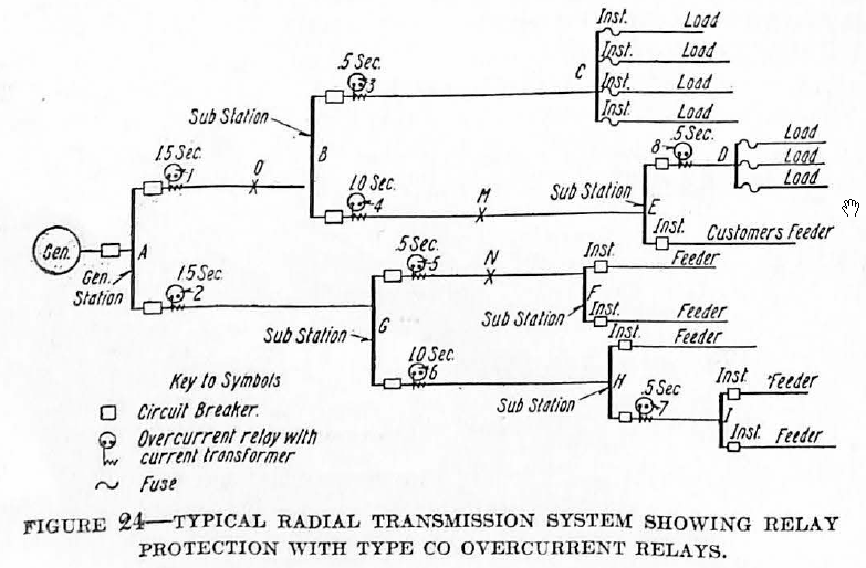
As we proceed back towards the generating station A, overcurrent relays such as the CO relays are necessary in conjunction with the circuit-breakers to give a definite time for tripping.
Assuming that there is a short circuit at M, the excess current will flow through relays Nos. 1 and 4, but No. 4 will trip in one second, thus cutting off the short circuited line before No. 1 has had time to trip. Likewise, with a fault at N. both relay Nos. 2 and 5 will be affected, but No. 5 will trip its breaker first.
It is common practice to allow approximately 0.5 second between successive relays and 2.0 seconds as the maximum permissible setting.
In addition to securing discrimination on the part of the relays by means of a definite-time feature, it is also possible to discriminate by the current setting, because trouble which occurs at the far end of one of the branch lines will not draw so heavy a current as if it were near the generating station. Relays, such as Nos. 7 and 8, Figure 24, on the remote lines may, therefore, be given a setting which will cause them to operate on a much lower current than will the relays near the generator.
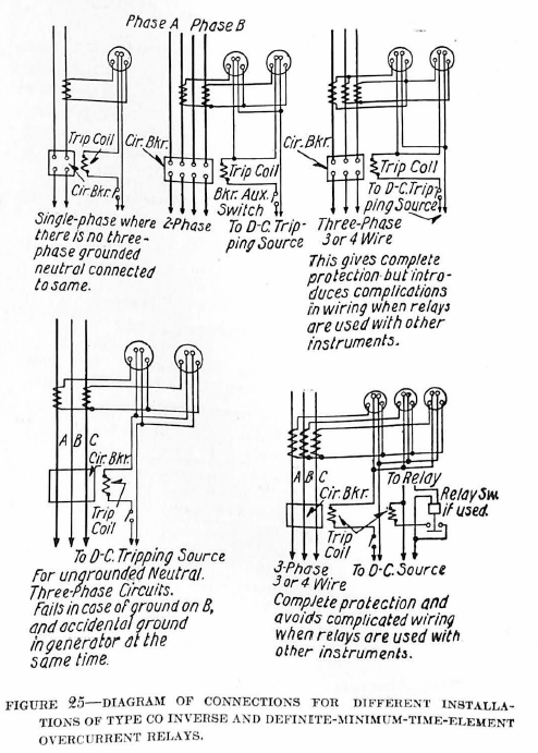
The Westinghouse CO relay is especially adapted for such installations because it combines the inverse and definite-minimum-time characteristics, and because it also may be set to operate on various values of current.
In radial systems in which the number of branches becomes so great that it is difficult to allow the necessary time setting between successive relays without making the time setting on the relays at the generating station extremely high, the CZ distance or impedance relay may be used instead of the CO relay. When this relay is used, the relay nearest the fault operates the quickest, thus making time settings unnecessary. This type of relay is slightly more expensive than the CO, and requires voltage connections in addition to the current connections.
The Ring or Loop System
The ring or loop system, as indicated by the name, is simply a continuous transmission line running through a series of substations and finally terminating at its starting point. This forms one of the best ways of securing uninterrupted service with a minimum expense for feeders. The number of substations which may be thus tied together depends upon the geographical location and the relay protection that is desired. Where the CO and CR relays are used, the number of stations is limited, due to the fact that the required time intervals necessary between successive relays add up to an unsafe value. With the advent of the CZ relay, however, this difficulty is largely removed.
On a simple loop system having only one source of power, directional overcurrent relays, with definite-time-limit characteristics, may be used for protection against short circuits. The time setting of each successive relay must be increased by an amount sufficient (usually 0.5 second in practice) to allow time for the circuit-breaker in the preceding substation to open.
The directional relays applied at each substation are fixed so that they will trip only when excess current is flowing away from the substation bus. It is, therefore, evident that with successive time settings the relays at each end of any faulty section will be the first to operate, serving to isolate this section of the loop. Straight overcurrent relays may be used at the generating station or source of power, as any fault on the system can cause power flow in only one direction from this point.
Fig. 26 shows a typical loop system tying-in four sub-stations with the generating station. It shows the application of directional overcurrent relays on each side of the substations and straight overcurrent relays at the generating station. The arrows indicate the direction in which the overcurrent must flow to trip the relay and the figures show the definite-minimum time setting of the relay.
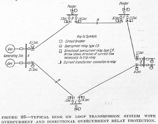
Considering a fault at M, current will flow to it from substations B and C. The 0.6 second relay will trip out the substation C end, and the 1.6 second relay at the substation B end. It should be noted that the same fault current flows through the 1.1 second relay at sub-station D in the proper direction and the 1.6 second relay at E. The relay at C, however, trips first, clearing the fault. This same current flows through the 0.6 second relay at D and the 0.1 second relay at E, but in the wrong direction to cause them to close their contacts. A fault at any point may be similarly checked out.
Where a loop system has more than one source of power, the application of relays becomes somewhat more complicated. The same type of relay may be applied with the same system of successive time-settings. One difficulty that is encountered in such a system is that if the relays are set for a condition with both sources of power connected, such settings must be changed somewhat when one source of power is disconnected. In this case, the entire relay system has to be readjusted. This illustrates the necessity for using relays whose adjustment can be changed quickly.
Types CO and CR Relays – The Westinghouse CO and CR relays are specially adaptable for use on loop systems as they embody the definite-time-limit characteristics with a very flexible adjustment for values of operating current. In addition to the dependable accuracy of the relay settings and the speed of action, any necessary changes in the settings or adjustments may be made quickly and conveniently.
Type CZ Impedance Relay – Sometimes it is very difficult to arrive at a suitable method of protection for a loop system due to the fact that, when applying the standard time-element relays and allowing the necessary time-intervals, in order to secure selectivity, the time-settings of the relays at the ends of the loop become necessarily higher than is either safe or advisable.
A more recent and flexible relay application for such complicated systems is the use of the impedance or distance relay developed by the Westinghouse Company. With the proper application of the CZ relay, all time-settings are taken care of automatically after each relay has been set to protect its own section of the line. Each relay is set to trip out its own section of the line in a time corresponding to the distance to the fault, the maximum time required being 0.75 second, which corresponds to a short at the far end of the line. Regardless of on what section of the system the fault takes place, the proper relay will trip out, and at no time will the isolation of the faulty line require more than 0.75 to 1.0 second to accomplish. The other CZ relays on other sections of the line will start to function but by reason of their greater distance from the fault they will not trip out their breakers, but will return to their normal position as soon as the relays on the faulty line have isolated the fault. This automatic increase in timing with increase in distance to the fault is the unique feature of a CZ installation.
With the addition of a directional element to the relay main element, this relay may be applied on loop systems in the same way as CO and CR relays. The choice between the use of the two applications is dependent mainly on the cost. The CO-CR application is preferable wherever it can be supplied satisfactorily, inasmuch as the relays themselves are less expensive and the CO relays do not require a voltage connection. Where the system is complicated, and the sections of sufficient length (long enough to give approximately 3% voltage drop between ends of the section), the CZ relay is applicable and should be used.
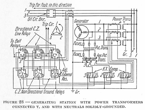
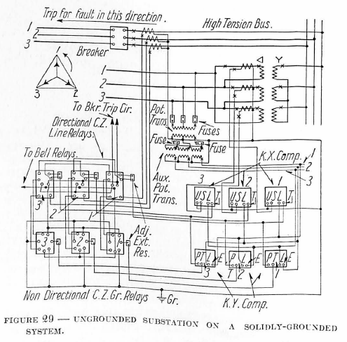
This voltage, which is a measure of the impedance voltage drop to the point of short circuit, is supplied to the voltage element of the relay by potential transformers connected either to the high or the low side of the power transformers. If connected, to the high side of the power transformers, the potential transformers will supply to the relay elements voltages corresponding exactly to the line voltage, and accordingly the relays will function properly. In case only potential transformers connected to the low side of the power transformers are available, it sometimes becomes necessary to use voltage compensators, similar to those used with voltage regulators, to compensate for the drop through the transformer which has been inserted between the relay and the line to be protected.
Compensators are provided:
(1) To compensate for the impedance drop in the power transformer, which drop is present when short-circuit current is flowing through the transformer into the line that is shorted.
(2) To compensate for the shift in the neutral at the ungrounded substation end of a solidly-grounded system, which shift occurs in case of an accidental ground on the high side.
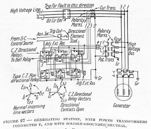
Figs. 27, 28 and 29 show typical CZ applications with and without compensation, as required.
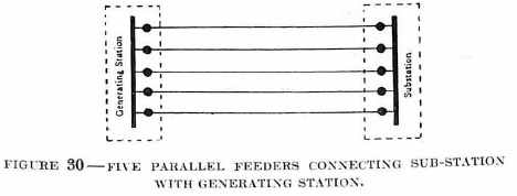
Protection of Parallel Feeders
Where two or more identical or similar lines connect a generating station and a substation, two substations or two generator stations, they are termed parallel feeders. Such an arrangement of feeders may be applied to either radial systems or loop systems and it has come into very common use due, not only to the fact that it is an economical and convenient means of increasing transmission capacity, but also, to the fact that it forms a most flexible system for economical operation of lines, and lends itself very readily to relay protection.
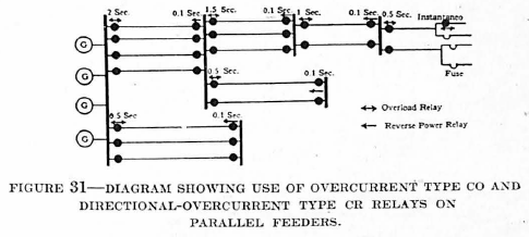
CO and CR Relay Scheme—In general, the standard application of CO overcurrent and CR directional overcurrent relays may be applied to parallel feeders in the same way as in the case of single lines of loop systems. Where the system is large, however, the time settings on some of the relays must necessarily be high in order to secure selectivity, and this in itself is often a difficulty which cannot be overcome.
Balanced Power Scheme—A general solution of this problem is to use a balanced system of relays. Separate parallel circuits which normally carry equal currents are balanced against one another. If the currents maintain their equality in spite of their magnitude it is a good indication that no fault exists in that particular group. On the other hand, a certain degree of unbalancing would be a safe indication of trouble. The problem, therefore, is in general, to separate a current which is representative of the actual unbalancing and pass it through proper relays so that the faulty feeder may be disconnected.
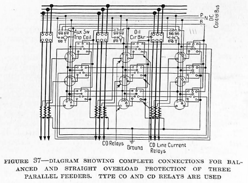
One method of solving this problem is by balancing the current flowing in the two feeders by the cross-connection of directional relays. This scheme may be applied to any system no matter how complex, if its feeders are run parallel between the switching points. The relays may be set to act almost instantaneously. With this system the relays can be set to operate on currents smaller than the full load value of each feeder. This arrangement enables the clearing of trouble on a system having the neutral grounded through a high resistance, when the total trouble and load current flowing through a single cable may be less than the maximum load current of that cable. The schematic diagram, Fig. 32, shows the scheme of cross-connection of directional relays applied to a system of four parallel feeders. Fig. 33 shows a complete diagram of standard connections for a pair of 3-phase feeders, except that the tripping circuit is omitted.
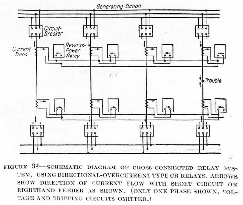
By reference to these two figures it will be seen that all the current transformers in the generating station are connected in series; likewise, those in the substation. Each relay is a uni-directional relay and is shunted across its own current transformer. Under normal conditions the load in each of the cables will be the same, and since the relays are of a higher impedance than the current transformers, the current from the latter will circulate through all of the transformers in series without any flowing through the relays. If the trouble occurs at any point outside the section protected by these cross-connected relays, the current through the protected lines will still be balanced and consequently there will be no unbalanced current tending to operate the relays. On the other hand, if trouble occurs on a line within the section, the current through the defective cable will be higher than that in the other and the excess current from its current transformer must, therefore, pass through the relays. While the system is in this unbalanced condition, current will flow through all the relays, but in the proper direction to cause only the relay at each end of the defective cable to act.
Fig. 33 shows auxiliary pallet switches connected in the transformer secondary circuit. These switches are also connected mechanically to the operating mechanism of the breaker so that, when the breaker opens, the current transformers on the feeder will be short circuited. By this method, a line can be cut out of service without interfering with the electrical balance in the remaining transformer circuit. However, these pallet switches are not needed in the transformer circuits except where low ratio bushing-type current transformers are used. Ordinarily the impedance of the current transformer secondaries is sufficient, when the primaries are open-circuited, to prevent any appreciable current from passing through them.
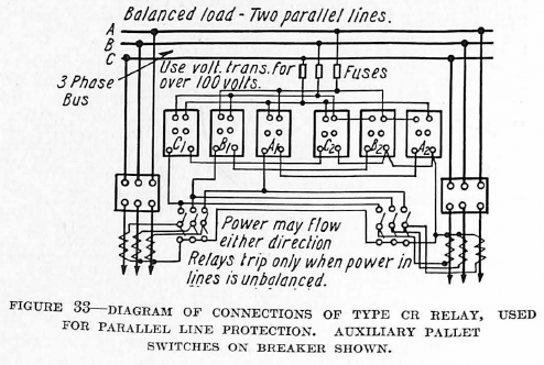
By referring to Figs. 32 and 33 it will be observed that under balanced conditions no current is flowing in the relay current coil. When a fault develops on one line the current and voltage in that group of relays are in such a relation as to close the directional element contacts, while in the other group of relays the voltage is in the opposite direction and so opens the directional element contacts. It is therefore apparent that if the directional element were made double throw, one set of relays could he made to protect two parallel feeders by cross-connecting the current transformers. Such a relay is available under the name of the Duo-Directional Type CR Relay. Its chief disadvantage is that either abnormal phase distortion or mechanical vibration may displace the relatively light directional element and trip the circuit-breaker before the fault has been isolated, thereby interrupting service over the good line.
A further adaptation of the cross-connected CR relay protective scheme gives both short-time low-current protection, when two feeders are operating in parallel, and long-time directional overcurrent protection when one of the feeders is operating singly as a part of a transmission loop. Fig. 34 shows the complete connections for two incoming feeders to a substation. The voltage and current connections to the relays are so made that the relays of each set close their directional element contacts when unbalanced power is flowing out over the line which those relays protect. Each relay is provided with a tap between the directional element contacts and the overcurrent element contacts and these taps are joined to a common bus for each pair of lines, so that any overcurrent element can trip either circuit-breaker by acting through the directional element contacts of the corresponding set of relays.
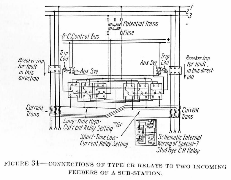
With the feeders carrying equal loads there is no current flowing through the current windings of the relays. As soon as a fault develops on one line an unbalanced current circulates through the relays, causing the directional element contacts on the faulty line group to close, and those of the good line group to open. The faulty line circuit-breaker is tripped by the closing of the contacts of the overcurrent element having the short-time setting.
As soon as the faulty line circuit-breaker has opened, the control circuit to the short-time overcurrent element is broken by the series connection through the circuit-breaker auxiliary switches. The remaining line then has directional overcurrent protection only, the time and current settings of the overcurrent element being determined by operating conditions on the loop. It is general practice to base such settings on the assumption that, with a loop composed of normally balanced lines, not more than two sections will be operating as single lines.
It is interesting to note that this scheme of connection obviates the use of a circuit-opening definite-time-delay direct-current relay to prevent improper operation of the good line circuit-breaker. It has been found necessary in many instances to employ such relays with cross-connected schemes in order to prevent unnecessary tripping.
Balanced-power relays are satisfactory particularly where there is no source of power available at one end of the parallel lines, but the use of differential current relays is simpler and is usually preferred where power can be supplied from both ends of the group of lines.
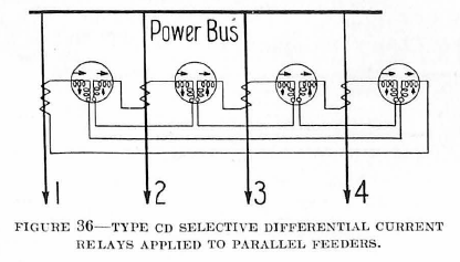
Type CD Selective Differential Relay Scheme – Another scheme which is coming into common use for parallel line protection is a scheme using the balanced current relay known as the type CD relay. It may be used at the transmitting end of any number of parallel lines and at the receiving end of any number of parallel lines in a system having a source of power at both ends, or at the receiving end of three or more parallel feeders in a radial system. It cannot be used on a single pair of radial parallel feeders, for in case of a fault on one line, there would be an equal and opposite current in the two elements, and the relay would not operate. The same condition will exist after one of three parallel lines has been disconnected at the receiving end. For this reason cross connected power directional relays are usually used at such points.
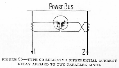
With three parallel lines protected by these relays, No. 1 line is balanced against No. 2; No. 2 line is balanced against No. 3 and No. 3 line is balanced against No. 1. In this way complete balance protection is secured until only one line remains in service, after which overload protection is left on this line. If four or more lines are thus protected, complete balanced protection cannot be assured after more than two lines have been removed from service. Thus, with four parallel lines, No. 1 line being balanced against No. 2, No. 2 against No. 3, No. 3 against No. 4, and No. 4 against No. 1, any one line can be disconnected and the remaining lines will still be balanced. If, however, Nos. 1 and 3 lines both have been disconnected Nos. 2 and 4 will be left with only overcurrent protection. On the other hand, if No. 2 or No. 4 lines were disconnected with No. 1 the remaining two lines would still be balanced.
Inasmuch as the action of the balanced-current relay is practically instantaneous in clearing faulty lines it makes an ideal application for the protection of parallel lines between generating stations. On other parallel feeders it is very often advisable to use overcurrent relays in connection with balanced current relays, thus securing single line protection in addition to quick balanced protection, when both lines are in service.
The chief advantages of the CD balanced-current relay scheme are as follows:
- The relay operates on current alone, no source of potential being required.
- The differential-current setting is automatically doubled when one line is opened at one end. This permits the use of a minimum-differential current setting and eliminates the necessity of additional apparatus in the trip circuit in order to render it non-automatic until the two lines are again in service.
- Each current transformer may be grounded, thus giving maximum protection to apparatus. This is not possible ordinarily with balanced protection.
- Only one relay is required for two lines.
- Relay action is practically instantaneous.
Type CZ Impedance Relay—The CZ impedance relay may be used for parallel line protection in the same way as the CO and CR relays. The CZ directional relay is applicable in places where the CR is used.
The advantages of the impedance relay have been explained in detail on page 20.
Network Systems
The simple radial and loop or ring systems, very often involving parallel lines between stations, lend themselves very readily to a scheme of relay protection, as has been outlined. However, when additional tie lines are added, connecting substations and several sources of power into the system at different points, it becomes what may be termed a network, and then the relay protection problem becomes more difficult.
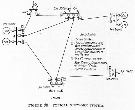
Type CO and CR Scheme—The CO overcurrent and CR directional overcurrent relays are sometimes applied to such a system, provision being made to have certain lines trip out almost instantly with a short circuit in their vicinity. With such an arrangement the network is often converted into a simple ring after the tie lines have been disconnected, and the usual scheme of time and current settings clears up the trouble. The cutting out of the tie line or lines in such cases does not in any way jeopardize the service, and serves to make selective relay protection possible. For example, in Figure 38 the tie line between substations E and B may he disconnected without disturbing the service supplied by the network.
Type CZ Impedance Relay Scheme—A more recent and flexible relay application for such complicated systems is the use of the impedance or distance relay. With the proper application of this type of relay all time settings are taken care of automatically, the inherent characteristics of the relay being such that the one nearest to the fault will operate first.
Pilot-Wire Scheme of Relay Protection
On systems where definite-time relay protection is desired, the number of substations which may be connected successively in a system is limited by the sum of the time intervals which it is necessary to allow between successive relays. When such a difficulty is encountered and the distance between some of the stations is small, a pilot-wire scheme of protection may be used on the shorter sections. As this scheme acts almost instantaneously upon the occurrence of a fault within the section, and is unaffected by the faults outside of the section, the section may be disregarded entirely when applying other relays. The system may be considered as if that particular section were entirely cut out.
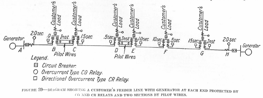
The pilot-wire scheme has current transformers at each end of the conductor short circuited upon each other through the pilot wire, see Fig. 40. The relays are connected between the pilot wire for each respective transformer and the common return. When a short circuit or fault occurs on the line between the two substations, the current transformers at the two ends are no longer short circuited upon each other, but the currents which they produce are opposed to each other so that current must flow through the relays, and the faulty section will thus be tripped out.
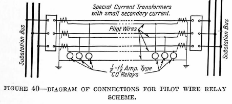
Inasmuch as the current flowing in the pilot wire must be kept at the minimum, special current transformers and CO relays with special windings to operate on low current are used for the pilot-wire protection scheme.
Split Conductor Scheme
The split conductor scheme is a modification of the current-balanced scheme of parallel-line protection in which a special cable is used to obtain a division of the current which is susceptible to being balanced. As ordinarily installed, the split-conductor cable is a three-strand cable in which the strands forming each conductor are separated into two parts, a central portion and a circumferential portion, the two being separated from each other by the necessary insulation. Thus, by the use of current transformers, a differential connection between the two halves of each conductor and overcurrent relays connected in the circuit, a very effective system of protection is obtained. This system is not widely used in the United States due largely, perhaps, to the high cost of the special cable.
Discover more from Valence Electrical Training Services
Subscribe to get the latest posts sent to your email.
Did you like this post?
You can share it with these links:
Read More Articles:
When I test induction disc relay type ... Is the pickup value the value at which the disc starts rotating?