Ask Chris: What is the difference between contactors, motor starters, relays and circuit breakers?
A reader submitted a question through the Ask Chris form. I’ve expanded the original question from “what are the differences between relays, contactors and motor starters?” to “What is the difference between contactors, motor starters, relays and circuit breakers?”
We’ll look at the history of electrical protection in this post to see how the difference between relays and circuit breakers evolved.
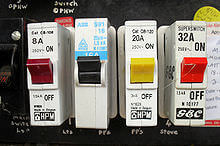
Switches
Switches allow the system operators to close electrical circuits so that electricity can flow into an electrical system. They range from simple knife switches like you see in Frankenstein movies, to the light switches in your house, to complex mechanisms designed to open and close in high-voltage systems. Switches have the following limitations in an electrical system:
- They are usually manually operated, which means someone must be present to energize or isolate a system.
- They are typically very slow. This means that under high loads or voltages, a dangerous arc can form when the switch is opened or closed.
- They are not typically designed to open a large amount of current. This means that switches can explode if they are opened when the current flowing through the switch is greater than its rating.
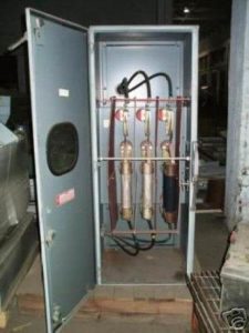
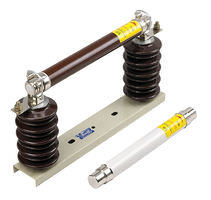
Fuses
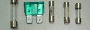
The early developers of electric systems quickly realized that you can get some spectacular explosions and damage when something goes wrong with electricity. The first protective device was probably unintentional as some part of the system simply melted away and isolated the rest of the system. This is the principle used in simple fuses. A fuse has two conductive ends and some kind of material between them that is intentionally designed to melt when the current through the fuse exceeds its rating. Fuses can range from simple household fuses, to complex current-limiting fuses designed to limit the amount of fault current that can flow through it.
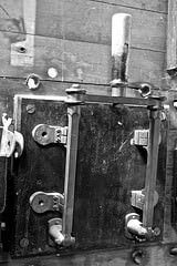
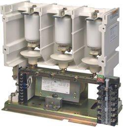
Circuit Breakers
Anyone who has replaced a fuse in their house or car can understand how inconvenient it is to:
- Find out where the fuse is
- See if you have the right fuse to replace it
- Remove and replace it
Now imagine that you are a lineman who has to:
- Find that fuse along power lines
- Carry a large variety of fuses for all of the possible applications
- Maneuver a stick long enough to reach the fuse on top of the power pole
- Replace the fuse and re-energize the high-power circuit, which is guaranteed to make a nice spark and loud bang
Circuit breakers combine the benefits of switches and fuses. A circuit breakers can energize or de-energize the system like a switch, but they have special mechanisms in place to open and close more quickly (<60-90ms). They also have arc-quenching technology to prevent arcs from forming because arcs are the start of electrical explosions. Most circuit breakers have control relays that tell the breaker when to open and close.
Some low-voltage circuit breakers can also isolate parts of the system when something goes wrong using their own fault detectors. The circuit breakers in your house typically use heat and metallurgy to detect faults. As current flows through the circuit breaker, it flows through two different metals that warp at different rates. When the current is too high for too long, the different metals move apart and operate the circuit breaker’s trip mechanism, which isolates the problem from the power source to minimize damage.
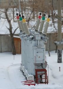
Most medium- and high-voltage circuit breakers, however, have a protective relay to tell the circuit breaker to open when a problem occurs in the system.
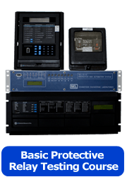
Protective Relays
There are two different classes of relays; protection relays and control relays. Protective relays monitor the electrical system and look for abnormalities. Some types of protective relays include:
- Electro-mechanical relays that rely on magnetism and mechanisms to detect a fault and send a signal to open the circuit breaker. Electro-mechanical relays are typically single-function, single-phase devices, which means that you need a lot of relays to protect a single feeder or source.
- Solid-state relays use electronic components to detect a fault, which then operate control relays to open the circuit breaker. Solid state relays are typically single-function, multi-phase relays which means you still need multiple relays to protect the system from different problems, but you can use fewer solid-state relays than electro-mechanical ones.
- Hybrid relays combine different features from electro-mechanical and solid-state relays and have the advantages and disadvantages of both.
- Digital relays use analog-digital converters, microprocessors, and algorithms to detect problems. The microprocessor operates control relays that tell the circuit breaker to operate. Digital relays are multi-function and multi-phase, which means you can use a single relay to protect any feeder or source.
A protective relay that could monitor thousands of amps, and hundreds of thousands of volts, would be HUGE and expensive. Most protective relays monitor the extremely high currents and voltages in a three-phase electric system through instrument transformers:
- Current Transformers (CTs) transform the thousands of amps flowing through an electrical system into a maximum of five amps in North America under normal load conditions, and one amp for most of the rest of the world. However, power system faults can inject more than 100A into protective relays, so they need to be accurate over a very wide range of current. (<5A under normal conditions, and more than 100A in fault conditions.)
- Voltage transformers (PTs or VTs) turn the extremely high voltages (480 to >500,000V) of an electrical system into a tolerable voltage (66 to 208V) that you could find in your house. Protective relays are able to fit into small panels because of voltage (potential) transformers.
Protective relays take the manageable voltages and current supplied by the instrument transformers and create a model of the current and voltage supplying a system. If the relay detects a problem, it will send a trip signal to the circuit breaker. Determining whether the system is normal or abnormal is often the hardest part of protective relay testing and design. Protective relays and circuit breakers must work together to detect faults and isolate those faults from the rest of the system.
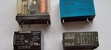
Control Relays
Control relays are used to relay messages (get it?) from one location to another. They can be used to turn one signal into many signals with multiple contacts, turn a low-voltage signal into a high-voltage signal, or visa-versa. Control relays come in many different flavors and can be found in nearly any electrical device more complicated than a toaster.
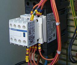
Contactors
A contactor is installed to provide the same function as a switch or circuit breaker, but has a completely different operating principle. When you move a switch or a circuit breaker into the closed position and then stop, the switch or circuit breaker will stay in that position. If the person who moves the switch isn’t present, or the system that sends the open signal to the breaker stops working, the switch and circuit breaker will stay closed until they either melt down or are opened by some other means. A contactor is held closed by an energized coil. If something happens to the power supply controlling a contactor, the contactor will immediately open. This is called a fail-safe system because if something unexpected goes wrong with the control circuit, the contactor will open and the system will be “safe”. If something happens to the control circuit of a circuit breaker, it will stay in whatever position it was before the problem, which may not be a “safe condition”. Contactors are typically used in motor applications to protect the motor, or the process the motor is used to operate, when something happens to the control system.
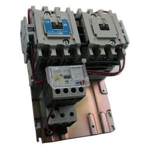
Motor Starter
A motor starter is a system that energizes and de-energizes a motor. A motor starter can have:
- A single contactor or circuit breaker
- A system of motor starters and auto-transformers for reduced-voltage motor starting
- Some kind of solid-state device like a variable frequency drive (VFD) that will control the waveform sent to the motor to provide some kind of controlled motor starting
A summary of the difference between contactors, motor starters, relays and circuit breakers.
Switches, circuit breakers, and contactors are used to control what parts of an electrical system are energized or de-energized.
Fuses are used to protect the electrical system when something goes wrong, and can isolate the faulted parts from the normal parts.
Circuit breakers can control and protect the electrical system, but most need a protective relay to determine if a problem exists and tell the circuit breaker to open. Control relays tell the circuit breaker to open and close under normal conditions.
A protective relay protects the electrical system by trying to determine what is normal and abnormal and tells the circuit breaker to open when a problem is detected. Protective relays and circuit breakers must work together to isolate a fault.
A contactor energizes and de-energizes a motor based on information from the motor starter control system.
A motor starter energizes and de-energizes a motor using a contactor, system of contactors, or other means.
I hope I answered the question! Please like, share, and/or add a comment or question. It helps us get noticed, which means we have more time to answer your questions and create free content like this.
Image credits:
- http://www.electronicrepairguide.com/
- http://www.openelectrical.org/
- https://www.flickr.com/photos/ddebold/5113676687/in/photostream/
- http://mssbllc.ecrater.com/
- http://en.wikipedia.org/wiki/Circuit_breaker
- http://simple.wikipedia.org/wiki/Relay
- http://www.ctiautomation.net/
- http://www.tecowestinghouse.com/
Discover more from Valence Electrical Training Services
Subscribe to get the latest posts sent to your email.
Did you like this post?
You can share it with these links:
Read More Articles:
Valence will be at the 32nd Hands-On Relay School
Dear,
Thanks a lot for the simple and nice explanation. These components are used so often but always without a very clear understanding of the basic differences between them.
Keep up the good work :)
Very nice explanation in a very simple and clear language.
Hi, I am trying to design a simple timer device that will open a circuit after the circuit has run continuously for a certain length of time – say 10 minutes, and will stay deactivated until manually reset. I know a timer device like this one may be a start, but where would I go from there. Thanks in advance and if this is not the correct venue to ask this question, please accept my apology.
Thanks for your comment. This is probably the wrong place for your question unless it is in a substation. It sounds like you need an off delay timer like the ones found here. http://www.alliedelec.com/search/results.aspx?term=off+delay+relay
Voltage transformers are VTs or PTs (not Pts or Cts) as stated.
Thanks for pointing out the typo. All fixed now.
Hi,
Thanks for a simply understandable and powerful explanation.
Few months back I had asked you different types of grounding method used in power system. Like Solid, Resistive, reactive and Isolated start points.
Can you please post something related to this ?
Thanks for the kind words.
We have a section on grounding methods in The Relay Testing Handbook
the functions and differences of switch, relays, contactors are beautifully explained in a simple way.
very good explaination for the fresh learner to understand the different on basic component. Thank you.
Dear Chris,
1. I have come across in many low voltage system that the “MCCB with build-in thermal and short circuit protection” are also designed and installed “with CT and protective relay”. To me the build-in protection of the MCCB and the protective relay functions would be duplicated in this sort of installation. I have asked around but I have not found any concrete explanation regarding this. Would you kindly explain what should be the correct practice ?
2) I have asked around how to do protection discrimination for Earth Fault (Ground Fault) protection. Again I have yet to find any concrete explanation and guidelines. Please kindly enlighten us on this.
Thank you.
Dominic Yong
2018-9-1
Thanks for your questions.
1. The only reason to have two different systems would be redundancy, or someone didn’t realize that the breakers already had overcurrent protection.
2. We concentrate on relay testing, not creating relay settings. Most ground overcurrent pickup settings are based on a standard for the location where the equipment will be installed.
It caught my attention when you said that circuit breakers can energize or de-energize the system like a switch, and they have control relays that tell them when to open and close. This is a great tip for industrial facilities that need to ensure that their power system is working efficiently to reduce downtimes. I could imagine how hiring a professional could help with circuit breaker testing as a part of the maintenance plan of a certain plant.
Really remarkable article to read on. I’m truly amazed by this article. Looking for far more info. You have explained very well about the control, relay and protection terms. The goal of the protection relay and circuit breakers is to identify a problem in the early stage, ideally, before it becomes serious, and to prevent or significantly decrease damage to persons and/or equipment. Thank you for sharing such knowledge.