Instrument Transformers from 1924 Silent Sentinels
Silent Sentinels 1924 Excerpt #17
This excerpt from the 1924 version of Silent Sentinels discusses how engineers applied instrument transformers in the early days of the electrical system. What differences can you spot when compared to the instrument transformers used today?
This is the final excerpt in the series. Follow these links to learn more about this series and the 1924 version of Silent Sentinels.
Instrument Transformers
Instrument transformers are used for two reasons; first, to protect station operators from contact with high-voltage circuits, and second, to permit the use of instruments with a reasonable amount of insulation and a reasonable current carrying capacity. The function of instrument transformers is to deliver to the instruments a current or voltage which shall be always proportional to the primary current or voltage, and which shall not exceed a safe potential above ground. Generally, the secondary of a voltage transformer is designed for about 115 volts and the secondary of a current transformer for 5 amperes, and both these secondary circuits are grounded, together with the cases of the relays, instruments or meters to which they are connected.
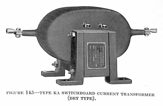
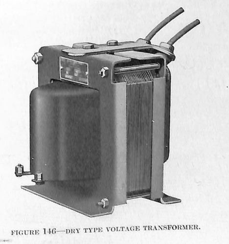
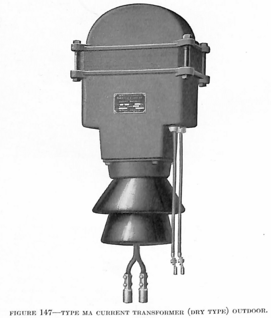
Types and Ratings—There are two general classes, of instrument transformers, dry and oil-insulated. Dry-type voltage transformers are listed for primary voltages up to the 6900-volt class and the oil-insulated type up to the 66,000-volt class. Current transformers are listed for primary currents up to 10,000 amperes. For voltage classes up to 23,000 volts, the dry type of current transformer is used, and for the higher voltages the oil-insulated type. The demand for transformers of higher ratings than those given is so small that they are not listed, although they can be built on special order.
Oil is used in oil-insulated instrument transformers, chiefly for its insulating properties. It is extremely important, therefore, that it be of the proper quality and that it be kept free from dirt and moisture.
Polarity—In connecting instrument transformers to wattmeters, watthour meters, power factor meters, etc., it is necessary to know the relative instantaneous direction of currents in the leads. For this reason one primary and one secondary lead of each Westinghouse transformer are marked with a white polarity marker. The relation of the marked leads is such that the instantaneous direction of the current in them is the same; that is, toward the transformer in the marked primary lead and from the transformer in the marked secondary lead, or vice versa. This marking of the leads is carefully checked by a polarity test.
Grounding of Secondary—All instrument transformers should be grounded on the secondary side as an extra precaution against danger from the high voltage in case the insulation should be punctured by lightning or other abnormal stresses. In polyphase groups, any point of the secondary may be grounded, but it is preferable to use a neutral point or a common wire between two transformers.
Insulation—The insulation of instrument transformers protects the meters and control apparatus as well as the power station operators from the high-voltage circuits. It is highly important, therefore, that it be able to withstand the strains of service. For this reason, the insulation of Westinghouse instrument transformers is designed with special care. Dry-type transformer coils are impregnated with a compound impervious to moisture. Coils for oil-insulated transformers are dipped in varnish or impregnated to seal them against moisture.
Insulation Tests—The insulation tests conform to the Standardization Rules of the A.I.E.E.
Voltage Transformers
Uses—Voltage transformers are used with voltmeters, wattmeters, watthour meters, power factor meters, frequency meters, synchronoscopes and synchronizing apparatus, protective and regulating relays, and the no-voltage and over-voltage trip coils of automatic circuit-breakers. One transformer can be used for a number of instruments at the same time, if the total current taken by the instruments does not exceed that for which the transformer is designed and compensated.
Voltage transformers have a capacity of 200 volt-amperes, but are compensated to give correct ratio at 40-volt-amperes, as this is the average load demanded of a voltage transformer. Special transformers may be compensated for correct ratio at any load up to the full capacity of 200 volt-amperes.
The standard secondary voltage is 115 volts (nominal) to suit standard instruments. Instrument transformers with special secondary voltages can be made if necessary.
Principle of Operation—The voltage transformer is, in principle, an ordinary constant potential transformer, especially designed for close regulation, so that the secondary voltage under any condition will be as nearly as possible a fixed percentage of the primary voltage.
The secondary voltage can never be exactly proportional to the primary voltage, or exactly opposite in phase to the primary voltage, on account of the losses in the transformer and the magnetic leakage between coils.
There are two classes of errors inherent in voltage transformers; ratio error and phase-angle error. The part of these errors due to the exciting current is constant for any particular voltage. It can be reduced to a minimum by choosing the best quality of iron and working it at a low magnetic density. The part of the errors due to the load current varies directly with the load and can be minimized by making the resistance and reactance of the windings very low.
Current Transformers
General—The current transformer is a special development of the transformer principle. The object is to maintain a constant ratio between the currents in the primary and secondary windings, instead of a constant ratio between voltages, which is the usual requirement.
Uses—Current transformers are used with ammeters, wattmeters, power factor meters, watthour meters, compensators, protective and regulating relays, and the trip coils of circuit-breakers.
One current transformer can be used to operate several instruments provided that the combined burden does not exceed that for which the transformer is designed and compensated.
Principle of Operation—The ordinary voltage transformer or distribution transformer is connected across the line and the magnetic flux in the core depends upon the primary voltage. For a given voltage the flux is, therefore, fixed, while the current in the winding rises and falls as the load of the secondary winding changes.
The current transformer is connected directly in series with the line. For a fixed number of instruments in the secondary (which is the usual condition) a rise or fall in the line current requires a corresponding rise or fall in the secondary voltage to force the secondary current through the impedance of the meter load. The magnetic flux in the iron, which supplies this voltage, thus follows the rise and fall of the primary or line current.
In any transformer, the primary ampere-turns may be considered as made up of two parts, one small element which supplies the magnetizing and core loss current, and another element which supplies the “working current.” The “working current” ampere-turns are always exactly equal to the secondary ampere-turns.
Discover more from Valence Electrical Training Services
Subscribe to get the latest posts sent to your email.
Did you like this post?
You can share it with these links:
Read More Articles:
Save Your Spot at the 33rd Annual Hands-On Relay School