Auxiliary Relays from 1924 Silent Sentinels
Silent Sentinels 1924 Excerpt #15
This excerpt from the 1924 version of Silent Sentinels discusses the most common auxiliary relays used in the early days of electrical systems. This is the 15th in the series. Follow these links to learn more about this series and the 1924 version of Silent Sentinels.
Westinghouse Protective and Control Relays
4- Auxiliary Relays
In the design of relays, as with any other line of apparatus, it is desirable to adhere to the simplest plan possible. Many relay applications require only a single, simple contact arrangement, while others require a more or less complex scheme of inter-connected contacts. Rather than complicate the design of any one type of relay to take care of these more complex applications, several different relays are sometimes used to accomplish the purpose desired. In such applications, one relay is usually responsible for starting the sequence of contact operations. This is termed the main or primary relay of the application. The other relays simply serve as contactors, their coil or coils being energized by the action of the primary relay. These relays are termed auxiliary control relays.
Type BT Transfer Relay
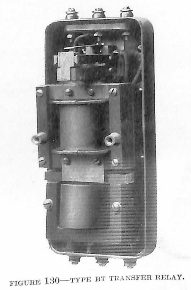
In most relay applications where the relay serves to energize the trip coil of a circuit-breaker, direct-current is used as the source of energy for the trip coil. In some cases, however, it is desired to use alternating-current taken from the current transformer to which the relay windings are connected. In such cases it is necessary to provide some contact arrangement whereby the secondary circuit of the current transformer will be closed at all times and whereby the trip coil of the circuit-breaker will be simply inserted in series with the transformer secondary, when the relay operates to energize the trip coil. The BT transfer relay is used in connection with the primary protective relays to accomplish this purpose. The main winding of the relay is connected in series with the secondary of the current transformer and the winding of the primary relay, and serves to hold the contacts in the normal position. When the primary relay closes its contacts they short-circuit an auxiliary winding on the BT relay and cause the contacts to operate and thereby cut the trip coil of the breaker into the circuit. The design of the contacts is such that when they are in the normal position the trip coil of the circuit-breaker is mechanically and electrically isolated from the current transformer circuit.
The windings of the relay are designed to carry 5 amperes continuously, but during times of short circuit they may be required to handle as much as 100 or 200 amperes. This can be done satisfactorily for a short period of time.
Type MC Multi-Contact Relay
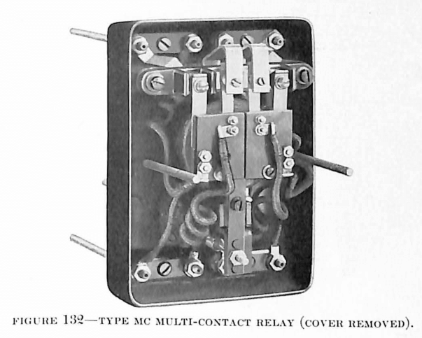
In the application of protective relays, it is often desirable to have several circuits energized at the time the primary relay operates. As most of the standard protective relays close only one or two circuits when they operate, auxiliary relays are necessary when it is essential to have more than the two circuits closed. Another case where an auxiliary relay is needed is when the current required in the control circuit, which is to be closed by the action of the primary relay, is greater than the contacts of the primary relay can safely handle. As in the case of the multiple circuit requirements, auxiliary relays are used to accomplish this purpose, the relay winding being energized by the closure of the primary relay contacts.
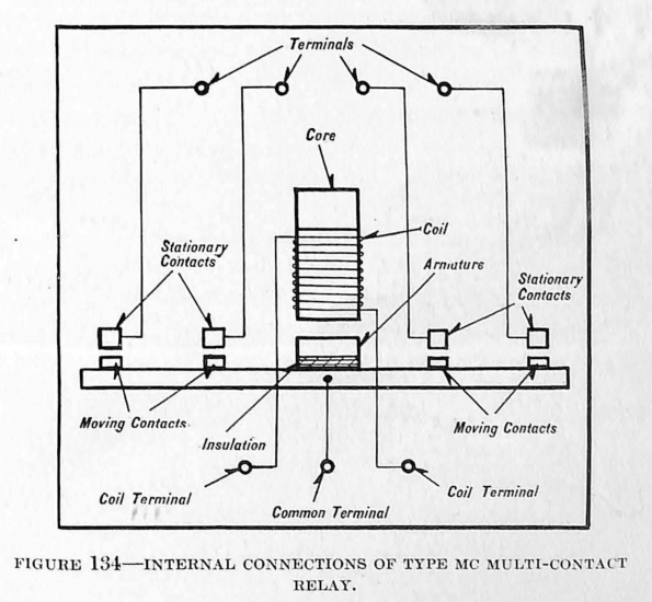
The MC multiple-contact relay fulfills either of the purposes just described and is used also in many other control installations where a simple multiple contactor is required. Its design is simple and such that it is suitable for operation either on alternating-current or direct-current circuits and may be allowed to remain energized continuously. The action of the relay is positive and windings may be supplied which are suitable for various values of alternating-current or direct-current voltage. There are also a variety of contact arrangements which may be supplied. The standard contact arrangements are:
- First – 4 independent makes
- Second – 3 makes, 1 break, all independent
- Third – 2 makes, 2 breaks, all independent
- Fourth – 1 make, 3 breaks, all independent
- Fifth – 5 makes, 1 break, all parallel
- Sixth – 1 independent make, 5 parallel breaks
- Seventh – 4 parallel and 1 independent makes
- Eighth – 6 parallel makes
Type M Multiple-Contact Relay
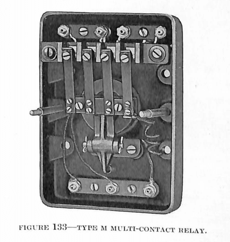
The Type M relay is similar to the MC, but is simpler: It is suitable for use only on direct-current, and is intended only for intermitted service. This relay is furnished with either 2, 4 or 6 contacts, the first having the independent, and the last two the parallel arrangement.
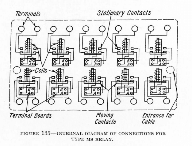
Type MS Banked Multicontact Relay
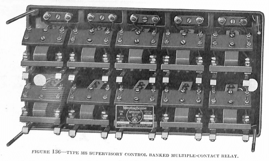
The MS relay consists of a group of 10 different and distinct contactors similar to the MC assemblies, except that each contactor operates only two contacts, or in other words, makes only 2 complete circuits. The 10 units are mounted in a neat case and the complete assembly is used on supervisory control systems wherever it is necessary to insulate the low-voltage telephone equipment from the higher-voltage power control circuit. The coils of these contactors may be supplied for various values of voltage and the entire group of relays may be applied to various applications wherever it is desirable to have a number of contactors in as compact an arrangement as possible.
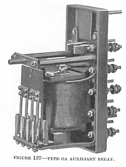
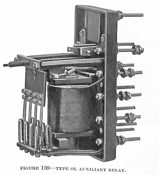
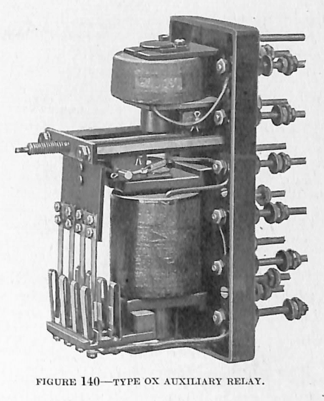
Type O Line of Auxiliary Relays
The O line of auxiliary relays is intended for miscellaneous switchboard and control use. Arrangement usually is such that the auxiliary relays are energized by protective or other primary relays, and they in turn energize or de-energize any desired combination of circuits. They have instantaneous time characteristics.
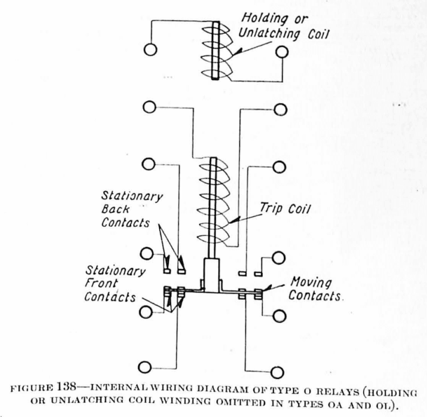
The O relays are so designed that when placed in the normal position, and with the main coil de-energized, they make a set of 4 contacts, and when in the operated position, a second set of 4 contacts.
The inter-connection between the 4 sets of contacts may be changed so that a large number of circuit combinations are obtainable, thus making the relay adaptable to a variety of applications.
There are 4 types of the O line of relays classified according to the method of resetting.
- Type OA—The OA relay has a main operating coil only and resets itself automatically as soon as the excitation is removed from the main coil.
- Type OL—The OL relay has only the main coil, but it has a latching mechanism which latches the contacts in the operated position as soon as the coil has been energized, and holds them until the latch mechanism is tripped by hand.
- Type OS—The OS relay is equipped with a main coil to operate the relay and also an auxiliary coil which serves, when energized, to hold the contacts in the operated position after the main coil has been de-energized. This type of relay resets automatically if the holding coil is not energized and otherwise resets when the holding coil is de-energized.
- Type OX-The OX relay is equipped with a main coil and also an auxiliary coil which is located similarly to that of the OS relay. It has the latching mechanism so arranged that when the relay operates the contacts are locked in the energized position until the latch is ripped either by means of energizing the auxiliary coil, or by hand.
Coils which are suitable for operation on various alternating-current and direct-current voltages may be supplied for the various types of relays. On account of vibration only the latching types are satisfactory on a-c. The contacts are of sturdy construction and will carry 10 amperes continuously, or will break 5 amperes at 500 volts, satisfactorily.
Type GK Long-Time Limit Relay
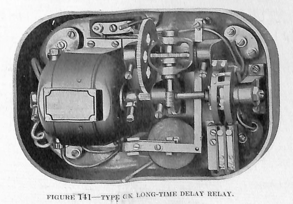
It often is desirable to introduce a time interval of considerable length between control switch operation, mechanical operation, or factory processes where a series of operations occur in sequence. A specific example of such application is in the case of automatic railway sub-stations where various operations must be correctly timed.
The GK relay is used for this purpose. It consists of a small motor driving a contact assembly through a train of gears. The contacts of this relay are carried on a drum connected to a worm gear. This worm gear is engaged with the driving gear by an electro-magnet, either simultaneously with the starting of the motor or at a certain definite interval after the motor has been started. The GK relays may be supplied with a time limit as high as 40 minutes. Relays whose time can be adjusted to from 1 to 10 minutes can be supplied on special orders.
Type JM Group Annunciator
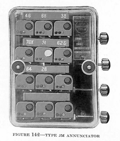
Many features in Electric Service Stations require operation indicators. To satisfy this need the Westinghouse Company has developed the Type JM Group Annunciator which comprises a group of twelve operation indicators assembled in a glass-covered case similar to that of the Type MC Relay.
The twelve indicators are mounted in four rows of three each and all are connected in parallel. That is, each has one terminal stud for one side of the line, and all the indicators are connected to a thirteenth stud which goes on the other side of the line.
The indicators of this Annunciator are similar in appearance to the Type C operation indicators described elsewhere in this book, but they differ somewhat from these in construction. The target, which is made of non-magnetic material, is latched in place behind the front plate. When the indicator coil is energized, the latch is pulled back, allowing the operating spring to pull the target into view.
All indicators can be seen readily through the glass cover of the relay. They are reset without removing the relay cover, by pulling a small knob which protrudes from the right side (front view) of the relay case. There is a separate reset knob for each row of indicators, or four for the relay.
Discover more from Valence Electrical Training Services
Subscribe to get the latest posts sent to your email.
Did you like this post?
You can share it with these links:
Read More Articles:
Instrument Transformers from 1924 Silent Sentinels