Direct-Current Relays from 1924 Silent Sentinels
Silent Sentinels 1924 Excerpt #13
This excerpt from the 1924 version of Silent Sentinels discusses the direct-current relays used in the early days of electrical systems. This is the 13th in the series. Follow these links to learn more about this series and the 1924 version of Silent Sentinels.
Westinghouse Protective and Control Relays
2-Direct-Current Relays
Installations where direct-current is employed are so few and small in size as compared with the present-day alternating-current installations that their importance is sometimes overlooked. It must be remembered that there are still many applications where alternating current cannot be used, or at least, where no means have yet been devised for using it instead of direct current. On such installations, therefore, it is important to have dependable relay service as protection against over-current, reverse current and other sources of trouble.
Type D Overcurrent Relay
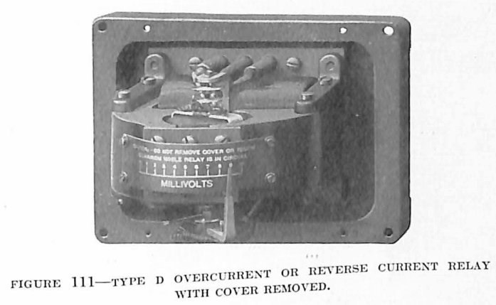
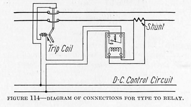
This type serves to furnish protection against overcurrent in direct-current circuits. The relay is of the moving coil type with an electromagnet energized by a voltage winding. The winding on the moving coil is connected across a shunt in series with the line and in this way receives a current proportional to the current flowing in the circuit to be protected.
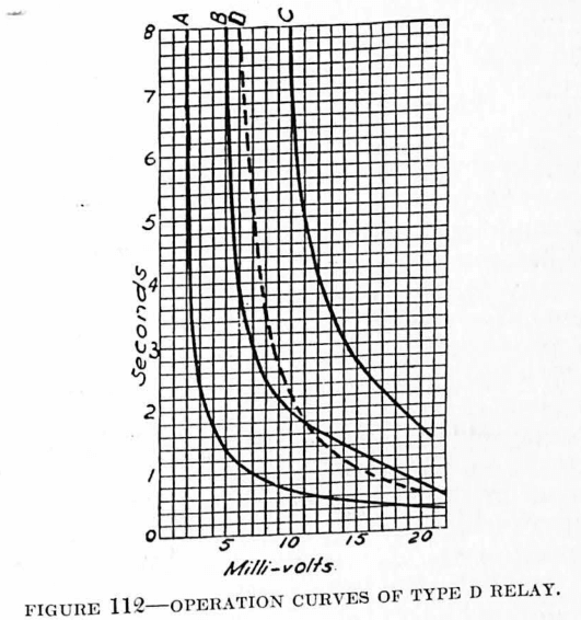
The moving contact is carried by the moving coil and is held open by the action of a spring. The torque produced by current flowing in the coil opposes the action of this spring, and when the current reaches any predetermined value the opposing action of the spring is overcome, and the contacts are closed. The electromagnet field is highly saturated and thus the action of the relay is unaffected by voltage changes. The overcurrent relay may be adjusted to operate over a range with from 40 to 80 millivolts impressed upon the winding.

Type D Reverse Current Relay
Conditions are often such that a reversal in the direction of current flow may prove very disastrous. For example, it requires a very small percentage of normal full-load current to cause a rotary converter to run away, when running inverted. A slight modification of the D overcurrent relay makes it serve as a highly sensitive reverse-current relay applicable for protection against such conditions.
The moving coil used in the D reverse-current relay is such that approximately two millivolts will cause the contacts to close. This tripping value may be adjusted to a smaller amount by changing the relative position of the moving and stationary contacts. By using shunts of different capacities in series with the line to be protected, almost any sensitivity required can be obtained.
For example, suppose the relay is set to operate on 1 millivolt drop in a given direction and is connected to a 100 millivolt shunt. It will then trip when approximately one per cent. of full-load current is flowing in the reverse direction.
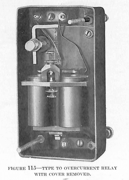
Type TO Overcurrent Relay
The TO relay serves practically the same purpose as the D overcurrent relay, except that its action is not as sensitive, and its construction is such that it can be supplied at a lower price. The relay consists of a two-pole electromagnet serving to attract a pivoted armature against the pull of a helical spring. The tension of the spring determines the tripping point of the relay. The relay is suitable for use with a 50-millivolt shunt, and may be adjusted to close contacts on from 40 to 80 millivolts.
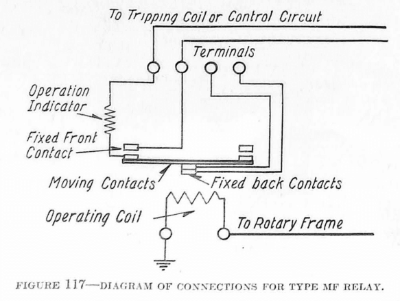
Type MF Flash Relay
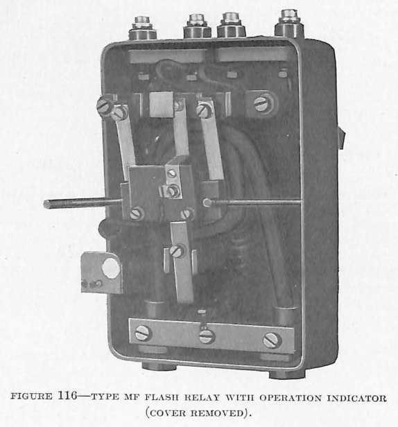
The flashing over of commutators on rotary converters has been the source of much trouble in the past, and, although the improvement of modern design has eliminated the possibility of such occurrences to some extent, the trouble still exists. The MF relay has been developed for the purpose of instantly disconnecting a machine upon the occurrence of a flash-over.
The MF relay operates by having an armature attraction close its contacts. The coil serving to attract the armature is connected directly between the frame of the machine and the ground. As flash-overs usually occur between insulated circuits and the frame of the machine, this arrangement will give immediately a flow of current to ground through the relay coil which acts almost instantaneously to disconnect the machine from the line. The action of the MF relay is so fast that with the ordinary flash-over, the machine will be disconnected before other protective relays farther back on the system have time to operate, thus cutting out the machine without disturbing the rest of the system. Its speed also aids in disconnecting the machine before any great damage has been done.
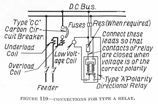
Type A Polarity Directional Relay
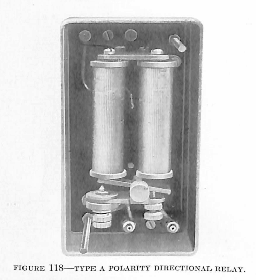
In many electro-chemical processes a current reversal even of small magnitude is serious, in many cases serious enough to cause considerable damage. Such conditions give reasons for the development of a relay to prevent any reversal of polarity. The Type A polarity directional relay fills the requirements for such protection and is applicable also to other uses where a check on the direction of polarity is desired.
The relay consists of a polarized electromagnet serving to attract a soft iron armature. The one pole of the permanent magnet consists of two steel cores upon which are placed the two coils of the relay. The relative action of the current flowing in these coils with respect to the pull of the permanent magnet on the soft iron armature determines the operation of the relay. Its sensitivity and design are such that the contacts will be closed upon any reversal of polarity of the circuit to which it is connected and upon the fall of the voltage to below 20% of normal. Upon the occurrence of an open circuit in the relay winding itself, action of the relay is assured before any voltage has built up in the reverse direction.
Type TV Voltage Relay
Wherever it is desired to protect direct-current circuits against excessive overvoltage or undervoltage a slight modification of the TO overcurrent relay may be used. The TO overcurrent relay with the coils wound for voltage constitutes the TV voltage relay, and is applicable for such voltage protection.
Discover more from Valence Electrical Training Services
Subscribe to get the latest posts sent to your email.
Did you like this post?
You can share it with these links:
Read More Articles:
Temperature Relays from 1924 Silent Sentinels