Some First-Generation Protective Relays from Silent Sentinels 1924
Silent Sentinels 1924 Excerpt #7
This excerpt from the 1924 version of Silent Sentinels lists some of the protective relays available in 1924. This is the 7th in the series. Follow these links to learn more about this series and the 1924 version of Silent Sentinels.
5 – The Protection of A-C. Apparatus
Overload Protection
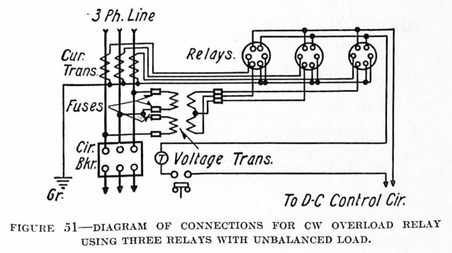
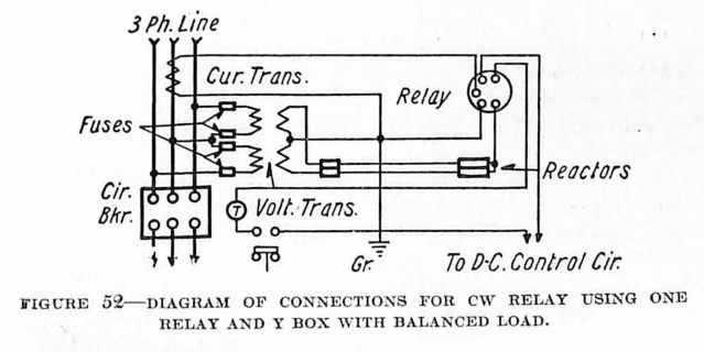
Overload protection of the larger type of electrical apparatus, as a general rule, receives little special attention inasmuch as the relays provided for short-circuit protection serve also for overload protection of the apparatus of the system. In addition to this, in generating and substations where there are operators in attendance, the load on the apparatus is usually under their supervision, and is governed by them accordingly, except in cases of short-circuit trouble on the system. In small installations where some scheme of overcurrent protection is necessary, the CO overcurrent relay, or the CW overpower relay can generally be used to give satisfactory protection.
Protection Against Internal Faults
Protection against internal faults in the windings of electrical apparatus is receiving much attention in present-day practice. These internal faults might be roughly classified as phase-to-phase short circuits, short-circuited turns, open circuits and grounds. Experience has shown that most of the internal faults developed in larger types of rotating electrical apparatus develop originally as a ground from the phase windings to the frame. If the neutral is not grounded, a fault of this sort will not unbalance the phase current, and it is, therefore, rather difficult to locate until it has developed into a phase-to-phase short circuit. Thus, from the consideration of protection, it is best, wherever possible, to have the neutral grounded.
Grounds are more likely to occur near the line end, rather than the neutral end of a winding, but in the event of the latter, the current which flows may be relatively small, especially if a high resistance ground is used. The fact that the fault current is often very small at the beginning, and that it is highly desirable to detect such a fault and disconnect the apparatus from the line before a phase-to-phase short circuit can develop, makes the protection of apparatus against internal faults rather a difficult problem.
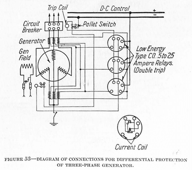
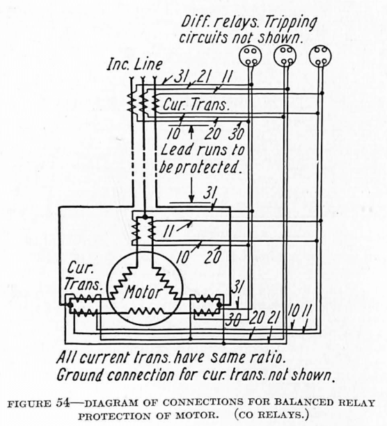
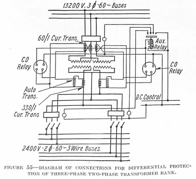
A differential scheme of protection, making use of either standard overcurrent relays, or special overcurrent relays operating on very small current, is the most general scheme for protection against internal faults. This form of protection consists of balancing the current entering the apparatus against the current flowing from it. This scheme of protection is usually accomplished by connecting a current transformer at each end of each phase winding, connecting their secondaries in series, and then connecting a current relay across these secondaries. As long as the secondary currents are equal, no current will flow through the relay windings. Any leakage of current, however, to other phases or to ground will upset this balance, and send current through the relay. The relay in turn operates to trip the circuit-breaker and disconnect the faulty apparatus.
The principle of operation used in this scheme allows relatively low-current settings on the overcurrent relays, because, obviously, no current will flow under normal conditions. It is also free from trouble due to circulating current, when synchronizing or switching on any part of the system is taking place, inasmuch as such current should be balanced in each phase. This scheme is very flexible in its application, and might be applied to machines of any size, either star or delta connection, provided that both ends of each phase winding are capable of being brought out and connected to current transformers.
No definite rule can be set down in regard to the size of apparatus to which relay protective schemes should be applied. It is largely a question to be decided from a consideration of the importance of limiting the amount of damage that can be done to the machine. In other words, it resolves into an economic consideration in which the cost of relay protection must be balanced against the value of service rendered, and then compared with the cost of possible damage to the apparatus.
In the case of large generators, and sometimes motors, where the neutral is grounded directly or through resistance, and the faulty currents may or may not be of any great value, a relay sensitive to very small current is required. The low-energy CO relay is especially adapted for the differential protection of such applications.
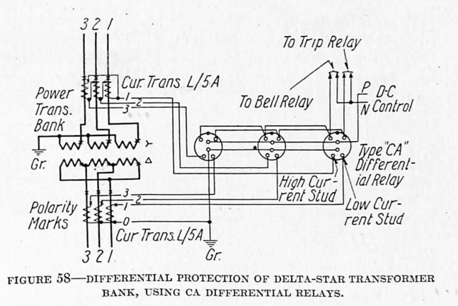
An improvement on this method has been made by designing a relay (the type CA) that trips on a percentage of the line current rather than on a given value of current. This makes it possible to get more sensitive protection without danger of having the relay operate due to the circulating currents, which usually occur at times of through short circuits.
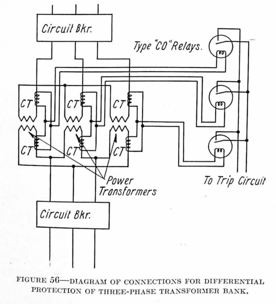
In the differential protection of transformers, highly sensitive settings are not so necessary, and in many cases are undesirable as they would only serve to disconnect the transformers upon some transient condition which accompanies a momentary unbalance, but not a fault. The standard overcurrent CO relay is, therefore, applicable for the differential protection of transformers.
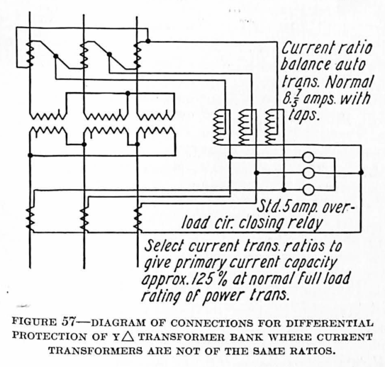
A special form of the type CA relay with taps provided so that unequal currents can be balanced without the use of auto transformers has been developed for transformer protection. This tap arrangement, combined with its adaptability to cases where circulating current appears under transient conditions, makes it of particular value, especially when bushing-type transformers are to be used.
Open or Reverse Phase Protection
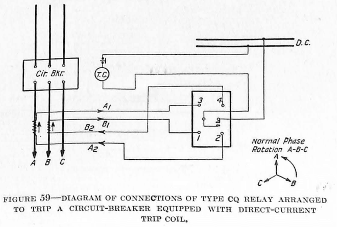
In many installations of polyphase motors, and rotary converters of any size, it is becoming a common practice to provide protection against running in case of an open phase, or in case of reversal of phases. A reversal of two phases, of course, reverses the direction of rotation of any motors on the line; and so it is especially desirable to have this condition protected against in cases where a reversal of the direction of rotation of any driving motor, such as one in elevator service, may be disastrous.
The CQ phase-balance current relay gives ample protection against the occurrence of such conditions on a system.
Temperature Protection of Windings
Inasmuch as the overheating of the windings in electrical apparatus is closely related to overcurrent protection, the overcurrent protection is often adequate to provide the necessary temperature protection. In some cases, however, it is more desirable to furnish protective apparatus which will include in its operation, not only the load on the apparatus, but also the existing temperature of the windings. In other cases, the temperature of the winding alone is taken as the determining factor in the operation of a temperature protective scheme.
In most of the larger generating stations or substations, where constant supervision of the operation of the various machines is possible, temperature indicating devices are used to show the attendant when the temperature of the windings in question becomes such that some means should be used to reduce it. Such indications are usually provided by means of exploring coils imbedded in the windings of the apparatus serving either to actuate a signal when the temperature reaches some predetermined point, or to operate some temperature indicating instrument. Thus when the critical degree of heat is indicated, the operator may relieve the condition either by reducing the load on the apparatus, or by increasing any existing cooling means, such as the flow of air or water, as the case may be.
Oil-Filled Thermal Relays – Where manual supervision is not possible, such as in automatic substation equipment, and in plants using numerous motors, it is necessary to have temperature protection that will disconnect the apparatus when any predetermined conditions exist. A common scheme for providing such protection is to apply in a protective relay a heating element with thermal characteristics similar to those of the machine to be protected. A current proportional to the load current in the apparatus itself flows through the heating element of the relay. The characteristics of this element are such that its temperature will be approximately the same as that of the protected apparatus under all loads and at all times. When the temperature of this element reaches the critical point, it serves to trip the apparatus off the line. The Westinghouse BA and BD oil-filled thermal relays serve to provide this class of protection.
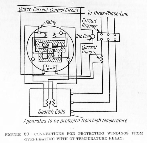
Type CT Temperature Relay – Another scheme used for the temperature protection of windings is to have the protective apparatus dependent on the current flowing at any given time, and also at the same time on the temperature within the windings of the apparatus to be protected. In such a scheme, the temperature is usually determined by means of copper exploring coils buried in the windings, and connected in some sort of bridge arrangement, so that the change in the resistance of the exploring coils, due to any change in the temperature of the windings, will give the proper temperature indication to the protective relay by using the change in the resistance values to cause a flow of current. In addition to this, a current proportional to the current flowing in the apparatus, flows through another winding of the relay, and thus the following three conditions are necessary before the apparatus is disconnected from the source of power. First, the temperature of the windings of the apparatus must be above the value for which the relay is set to operate; second, the current flowing in the apparatus must be above the normal value; and third, these two conditions must have existed for a given period of time. Thus the liability of the machines being disconnected upon the occurrence of a transient overload is guarded against. The CT temperature relay provides such protection, and embodies the necessary characteristics to assure maximum continuity of service.
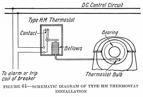
The simplest form of overtemperature protection is that in which the temperature of the surrounding material is alone used as an indication of the temperature of the winding, and is taken as the determining factor in the operation of any protective relays used. Such a scheme is used largely in the protection of transformers where the exploring coils, expansion bulbs, or whatever means are used for measuring the temperature of the surrounding material, may be embedded between the coils of the transformers in such a way that an approximate indication of the temperature of the windings is secured. The HM thermostat relay is sometimes used for this purpose.
Temperature Protection of Bearings
In the case of rotating machinery, it is often necessary to provide some scheme of protection whereby any overheating in the bearings will either cause a signal to operate, or else cause the machine to be disconnected entirely. Where actual supervision is possible, such protection may provide only for the operation of a signal to call the attendant’s attention to the fact that all is not well with his machinery. In cases such as automatic substations, it is usually necessary to have the protective apparatus disconnect the machine entirely, either shutting down the station or else disconnecting the individual piece of apparatus. The HM thermostat relay is used largely for this application.
Discover more from Valence Electrical Training Services
Subscribe to get the latest posts sent to your email.
Did you like this post?
You can share it with these links:
Read More Articles:
What Electromechanical Relay Kicked Your Ass?