Calculation of Short-Circuit Current from Silent Sentinels 1924
Silent Sentinels 1924 Excerpt #6
This excerpt from the 1924 version of Silent Sentinels discusses how electrical engineers calculated short-circuit currents operated in 1924. This is the 6th in the series. Follow these links to learn more about this series and the 1924 version of Silent Sentinels.
4 – Calculation of Short-Circuit Current
In applying any protective scheme it is necessary to determine the short-circuit currents which may develop under all conditions. It is unfortunate that the term “overload” has ever come into use in connection with sectionalizing distribution systems, because it implies that the relays should be set to operate at a value determined by the normal load on the feeder. Such a setting is possible if definite-time-limit relays are used, but where a relay having inverse-time characteristics is used it is necessary to consider the current that occurs during times of trouble, and that may be tens or even hundreds of times greater than the normal current. An approximate method of determining the possible short-circuit current is to observe the voltage drop between two stations at normal load.
Short-circuit current = (normal voltage/voltage drop) x load current
For example, if a certain load current causes a drop of five per cent. in voltage between a generating station and substation, the maximum short-circuit current would be 20 times the load current. Results obtained in this way are likely to be too large, particularly on lines having high inductance.
In order to determine more accurately the r.m.s. current, an analysis of short-circuit phenomena on an alternating-current network is necessary, and it may be desirable to call attention to some of the conditions under which relays may be called upon to function.
A short circuit is a transient condition and this current at any point in an electrical system is a variable depending on the resistance, inductance, electrostatic capacity, magnetic capacity, point on the voltage wave at which the disturbance takes place, and current conditions of the circuit immediately preceding any change in the steady condition of that circuit. It represents a readjustment of the stored electro-magnetic and electrostatic energy in the system from an initial steady condition until a final steady condition is reached. It is manifested during every change in the steady condition of the circuit, although its effects on the circuit are usually not appreciable. Under certain conditions, such as short circuits, the effects of the transient current, however, are of prime importance.
Short-Circuiting a system at any point immediately causes an abnormal current rush to occur on that system. During the first complete cycle following the short circuit, the current usually rises to maximum value. If, now, the generator field circuit is assumed to remain unchanged by automatic generator-voltage regulators or similar devices, then, during succeeding cycles, the current will rise to lesser and lesser values until a steady condition again exists on the system. The current wave during the transient period, as shown by oscillograms, may be symmetrical or asymmetrical with respect to the line representing zero current, depending upon the point on the voltage (pressure) wave at which the short circuit occurred. The transient current is said to be symmetrical when the assumed line, connecting points on the current wave midway between the peaks, coincides with the line of zero current. Similarly, a transient current is said to be symmetrical when the assumed line connecting points on the current wave midway between the peaks does not coincide with the line of the zero current.
The value of the current at any point on the current wave during the transient condition, if referred to, the line representing zero current, is a measure of the effects produced by the current at that point. Some of these effects are indicated by the breaking of insulators supporting busses, the displacing of windings of transformers and generators, the distortion of oil circuit-breaker connections, and the fusing of conductors in various parts of electrical systems.
The value of the current at any point on the current wave during the transient condition is frequently referred to an assumed zero line between the peaks. This value is used to calculate the electrical constants of a circuit, such as impedance, reactance, etc.
The maximum asymmetrical value of a transient current in r.m.s. amperes during a short circuit on an ordinary alternating-current generator is approximately equal to 1.8 times the generated voltage (pressure) of the generator, in volts, immediately preceding the short circuit, divided by the impedance of the circuit in ohms between the point of power supply and the point of short circuit. The maximum symmetrical value of the transient current is approximately equal to 0.55 times the maximum asymmetrical value.
The transient of an electrical system at a point remote from the source of power supply will be different from that at the terminals of an alternating-current generator. Its amplitude and duration will depend upon the electrical constants of the system and the distance between the point of short circuit and the source of power supply. In general, the greater the distance between the source of power and the point of short circuit, the less the amplitude of the transient and the shorter its duration. Automatic generator-voltage regulators introduce system transients differing from those which occur in systems not so equipped. They tend to maintain constant the system pressure, but on account of the inherent time lag of the iron portions of the generator and exciter armatures and fields, their effect is not felt immediately. The effect of automatic voltage regulators on system transients may be predicted for any known set of conditions and account taken of such effects in the application of relays.
Fig. 45 is a typical oscillogram showing the current flowing in one phase of the external circuit when a system is short circuited under ordinary operating conditions. In this diagram O is the origin of the co-ordinates and is taken at the instant at which the short circuit occurs, OX is the axis of abscissae, and the abscissae represent time. OY is the axis of ordinates, and the ordinates represent current. CD is a curve passing through the maxima of the wave of the total current, and EF is a curve passing through the minima. AB is a curve which cuts the vertical everywhere midway between CD and EF.
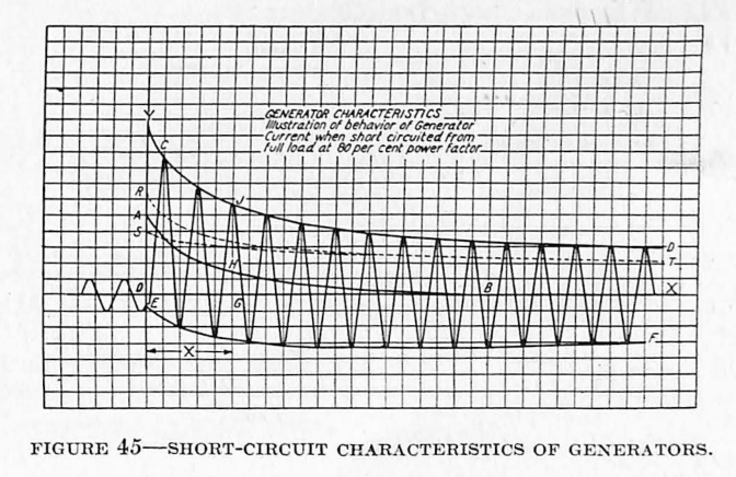
The wave of total current of which the crests lie along curve CD and EF and of which the ordinates are measured from the axis OX may be regarded as having two components, namely:
- A direct component.
- An alternating component.
The direct component is represented at any time by the ordinate to the curve AB or at the time X by the ordinate GH.
The alternating component is a wave whose crest value at any time is the difference between the ordinates to the curves CD and AB. This difference, at the time X, has the value HJ. The r.m.s. values of this alternating component are shown on curve ST. At any instant this component is considered to have the same r.m.s. value as an alternating wave of constant amplitude whose crest value is represented by one-half the distance between curves CD and EF at that instant.
The r.m.s. value of the total current wave under short circuit, at any instant, is the square root of the sum of the squares of the value of the direct component and the effective value of the alternating component at that instant.
The correct application of relays to an electrical system requires that certain characteristics of the system be known or assumed.
These system characteristics are:
- Normal voltage.
- Maximum current carried by the circuit in which the relay is connected.
- Normal frequency.
- Maximum kv-a. capacity of synchronous apparatus, transformers, reactors, and lines.
- Transient current characteristics during short circuit or overload.
The r.m.s. current at any point of a system under short-circuit conditions is affected by the following factors:
- The total kv-a., reactance and transient characteristics of the synchronous machines connected to the system.
- Number, reactance, resistance, capacitance and arrangement of all circuits over which power can be supplied to the point of short circuit.
- Kv-a., arrangement, resistance, reactance and capacitance of all reactors and transformers through which power can be supplied to the point of short circuit.
- Contact resistance at the short circuit.
- The nature of the short circuit, whether single-phase or polyphase.
- The kv-a. and power factor of the load being carried at the time of short circuit.
- The point of the voltage (pressure) wave at which the short circuit was established.
- The use of automatic voltage regulators.
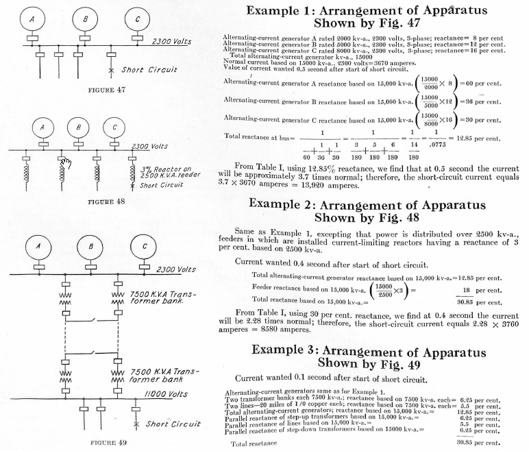
The short-circuit transient for systems may be determined by test, by calculation or, less closely, by assumption. Obviously, the determination by test for all circuits of a large system is expensive and involves considerable time and interruption to service. This will be practicable in but few cases. The determination by calculation is also a matter of considerable labor, but is feasible if only the important factors listed above are considered. Practical approximate selection, sufficiently accurate for most cases, can be made by using only reactance and an accepted group of time-current decrement curves.
Table I gives decrement factors for three-phase short circuits. These factors are intended primarily for use in relay application and setting, where minimum short-circuit values are important.
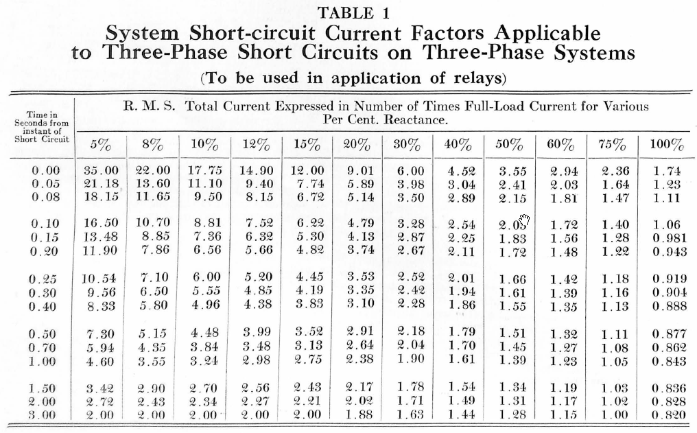
The effect of using r.m.s. values instead of peak values is to appreciably reduce the ratio between short circuit and rated amperes. For example, assuming ten per cent. reactance and a short-circuit current containing the maximum possible direct component, the ratio of the peak value of the first alternation of the short-circuit current to the peak value of rated current is roughly twenty. Under the same conditions the ratio of the r.m.s. value of the first alternation of the short-circuit current to the r.m.s. value of the sinusoidal rated current is roughly seventeen.
The effect of using the flux at rated voltage and the assumed load, instead of at rated voltage and no load, is to increase the short-circuit current by a somewhat lower percentage than the alternator reactance percentage. This effect in alternating-current generators of low reactance is relatively unimportant, but becomes of increasing importance as the generator reactance increases.
The characteristic shapes of the time-current decrement curves have been reached by analysis of generator tests including oscillograph studies of short circuits occurring when the generators were excited to full voltage and were carrying various loads at various power factors.
In the curves for total reactances up to and including 15 per cent., the reactance is assumed to be wholly within the alternating-current generators and for higher values of reactance the generators were taken at 15 per cent. and due allowance made by calculation for the effect of the external reactances. In the latter case, if alternating-current generators of other reactance had been used the results would have been somewhat different but the error is not large enough to be of practical importance.
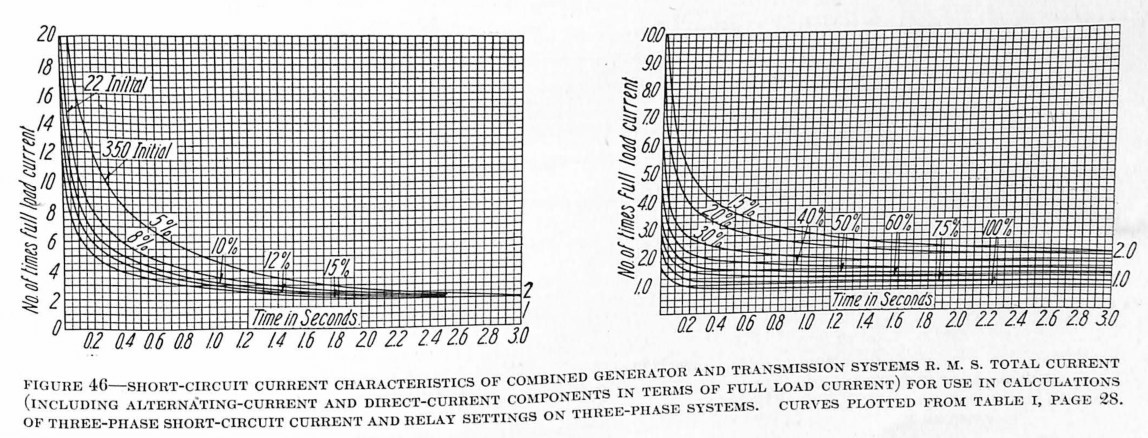
The final values of the current, i. e., the sustained short-circuit current, have been assumed in accordance with experience and tests and are based on the behavior of machines of predominating design.
The study of representative oscillograms of short-circuit tests showed that in most cases the direct component disappeared within 0.5 second and that the transient portion of the alternating component disappeared within 3.0 seconds. These time values have therefore been used in constructing the characteristic decrement curves.
Several alternating-current generators with the same reactance and synchronous impedance will not necessarily have the same rate of r.m.s. current decay. This has been considered in constructing the characteristic curves, and the decrement curves may therefore safely be taken as representing the greatest r.m.s. current that will be given by modern alternating-current generators of normal design.
The percentage reactance in any leg of a circuit is the reactance drop in that leg of the circuit at normal rated current expressed as a per cent. of the voltage to the neutral of that circuit. For single and two-phase systems this is the voltage between phase wires divided by 2. For three-phase systems this is the voltage between phase wires divided by 1.73. The percentage values in Table I are initial values based on a symmetrical sine wave and on the maximum rating of the machines connected to the bus. The percentage of reactance of generators varies from about 8 per cent. to 30 per cent. The percentage reactance of transformers varies from about 3 per cent. to 15 per cent.
Nature of Short Circuits – When making current calculations it should always be assumed that a short-circuit is due to a metallic connection between the conductors. In a high-voltage aerial line using wooden pins and cross-arms it sometimes happens that an insulator is broken, with the result that the wood is gradually heated by the passage of the current through it until it finally bursts into flame, thus causing an arc between conductors. A little consideration shows that the flow of current is small until the arc is established, and that it is wrong to speak of automatically disconnecting a section of line which has such a high-resistance short-circuit. It has sometimes been assumed that an arc has a high resistance, but this is not the case, and in general the presence of an arc at the point of short-circuit will not decrease the short-circuit current by more than a few per cent. Incidentally, it may be of interest to note that on a high-voltage ungrounded-neutral system the capacity current to ground through an arc is greater than it is through a direct ground. There is only one case where a short-circuit is likely to increase in intensity as it develops, and that is on a system where the neutral is grounded through a resistance. A cable breakdown, for instance, frequently occurs first between one conductor and the sheath and the current flow may be limited by the neutral resistance; the trouble will quickly involve all the conductors in the cable, resulting in a heavy short-circuit, but it is possible that it will require an appreciable time to do this, in which case the relay operation may be unsatisfactory. This is particularly liable to happen if the neutral is not grounded at every substation.
Discover more from Valence Electrical Training Services
Subscribe to get the latest posts sent to your email.
Did you like this post?
You can share it with these links:
Read More Articles:
Valence will be at the 32nd Annual Hands-On Relay School in Pullman, WA