Westinghouse Protective and Control Relays from 1924 Silent Sentinels
Silent Sentinels 1924 Excerpt #12
This excerpt from the 1924 version of Silent Sentinels lists the protective and control relays used in the early days of electrical systems. This is the 12th in the series. Follow these links to learn more about this series and the 1924 version of Silent Sentinels.
Westinghouse Protective and Control Relays
1 – Alternating-Current Relays
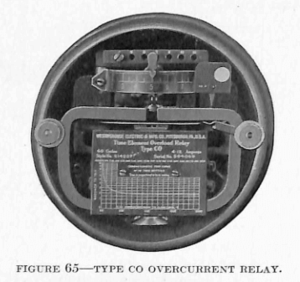
Type CO Overcurrent Relay
The protective relay now having the most universal application is one that may be used to disconnect circuits or apparatus, when the current flowing in the circuits or apparatus exceeds any given value. Such a relay has a wide variety of uses. The most common uses are applications to outgoing feeders, transmission lines, generating and substations, distribution feeders at substations and to motor and transformer circuits. A relay designed for such a diversity of applications must have very reliable characteristics which will allow a flexible adjustment for operation under all circumstances and conditions.
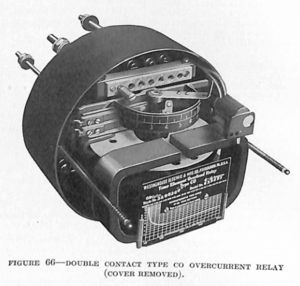
Inverse-Time Characteristics—The CO overcurrent relay embodies characteristics which make it applicable to the widest variety of uses for overcurrent protection. The relay is similar in operation to the OA watthour meter. It operates on the induction principle, the contacts being closed by the rotation of a disc. It is necessary to have a certain quantity of current flowing in the relay winding before the disc will begin to rotate. After it once has been started the speed of rotation is proportional to the current flowing in the winding until such current reaches an excessively high value. This gives the relay an inverse-time characteristic or, in other words, the greater the current flowing in the relay winding the sooner the relay contacts will close. The design of the relay and the action of the damping magnet are such that the time of action is definite for any given current value.
Definite-Minimum Time Characteristics—Conditions arise in overcurrent protection which demand that a relay used for such a purpose should never close its contacts instantaneously. Because of the inverse characteristics of the CO relay it is evident that upon excessive overcurrent the action of the relay would become almost instantaneous. A small torque compensator is added in the relay winding for the purpose of placing a definite limit to the inverse-time characteristic. This compensator becomes saturated at excessively high currents and acts upon the relay in such a way that a definite-minimum time must elapse before the contacts will close regardless of the value of current flowing in the winding. This is termed the definite-minimum time characteristic of the relay.
Current Settings—Conditions very often arise where the current supply used for operating an overcurrent relay varies widely due to different current transformer ratios, different conditions under which the relay is desired in act and different degrees of sensitivity required in the relay. Such an adjustment of operating current is obtained in the CO relay by varying the number of active turns in the main coil winding. This is accomplished by means of a screw in the terminal block at the top of the relay element. The numbers on this terminal block represent the minimum current which will operate the relay.

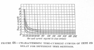
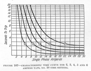
Time Settings—It is also very often desired to vary the time in which the contacts will close when any given amount of current is flowing in the relay winding. This adjustment is accomplished in the CO relay by varying the distance through which the disc must rotate before the contacts are closed. This distance through which the disc must travel is adjusted by means of the scale and hand lever located directly above the disc. The time-current curve shown on the nameplate of each relay gives the time required for the contacts to close with different values of current flowing in the relay winding with the time lever set on the No. 10 graduation. It will be noted from this curve that two seconds is the minimum time in which the relay will close its contacts for any value of current regardless of how great it may be. This definite-minimum time may be reduced, of course, by placing the time lever on a smaller setting. For instance, if the lever is placed on the No. 1 graduation, the action of the relay will be almost instantaneous, because the disc has practically no distance through which it must rotate before the contacts are closed. (See Fig. 68.)
Contact troubles have always been very plentiful in relay operation. This source of trouble has been largely eliminated from the CO relay by introducing an auxiliary contactor switch inter-connected with the tripping contacts so that it closes the instant that the main relay contacts close. This arrangement relieves the relay main contacts from carrying the tripping current and also assures good contact, even though barely enough current is flowing in the relay winding to close the main contacts. The action of the contacts responsible for making the tripping circuit is, therefore, made positive and a tripping current of as high as 30 amperes may be safely handled without fear of contact trouble.
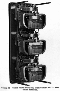
Type COA Overcurrent Relay
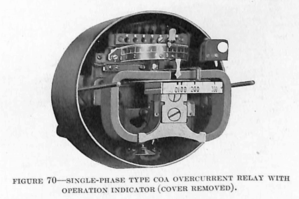
In many power plants and substations the space for mounting instruments and other switchboard apparatus is limited. In such stations it is often very essential also to have supervision over the current flowing in each circuit leading out from the station. A means of providing this current supervision and also relay protection for each circuit without the necessity of supplying and providing room for mounting both ammeters and relays, is provided by the COA relay.
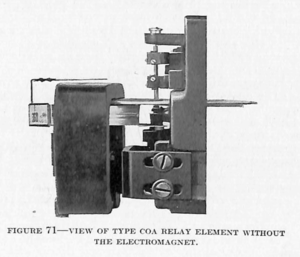
This relay consists of the CO relay with the addition of a current indicator which serves to show at all times the value of the current flowing in the circuit. The current indicator consists of a thin copper segment mounted on a separate shaft directly above the main disc of the relay in such a way that it is actuated by the same flux that passes through the relay disc. As the relay winding is connected directly in the circuit to be protected by means of a current transformer, the current indicating element shows at all times the quantity of current flowing in the line. The current indicating element also gives a double protective assurance, inasmuch as any accident which occurs either within or without the relay to prevent the main electro-magnet from operating the relay disc will also keep the indicating disc from operating.
Low Energy Type CO Relay
Certain relay applications are such that only very little energy is available for operating the relay. This is especially the case on high-voltage lines where low-ratio bushing-type current transformers are the only convenient means for supplying energy for the operation of relays or instruments.
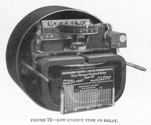
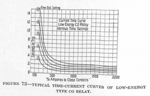
A modification of the CO relay has been designed to fit such conditions. This low-energy CO relay requires approximately 2 volt-amperes for tripping. In construction and operation it is very similar to the standard CO relay, except that the contacts are not closed directly by the action of the disc but through a train of gears. This train of gears also supplies the definite-minimum time characteristics, thus eliminating the torque compensator. Due to the construction of the relay it is somewhat more sensitive than the other CO relays and is, therefore, suitable for use on applications requiring great sensitivity. The differential protection of generators is an example of this type of application.
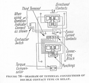
Type CR Directional Relay
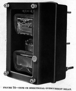
All relays dependent on current alone for their operation function when sufficient current is flowing in the winding regardless of the direction of the flow. In protecting transmission lines and in making possible the sectionalizing of such lines on the occurrence of trouble, it is often necessary to have protective relays which will close their contacts only when current is flowing in one certain direction.
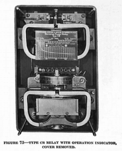
The CR relay has been developed to fill these requirements. The CR directional relay is a combination of the CO overcurrent relay and a watt element. The current element is the same as that of the standard CO overcurrent relay and has identical operating characteristics. The watt element is similar to the CW power relay except that it operates on a very small percentage of normal voltage. The contacts of the overcurrent element are connected in series with the contacts of the watt element and as this element will close its contacts only when the power flows in one direction, the relay as a unit operates only when current is flowing in any given direction. As the relay has all the characteristics of the CO relay, the following conditions must exist before the tripping circuit is completed: (1) Excess current must be flowing; (2) current must be flowing away from the bus bars or in the direction for which the relay is connected; (3) current must be flowing for a sufficient length of time. Thus the directional element may close its contacts upon momentary surges of current in the reverse direction, or the overcurrent element may close its contacts on the flow of excess current in the normal direction, but the tripping circuit is completed only when both elements close their contacts.
Low-Energy Type CR Directional Relay
The low-energy CR directional relay has been developed to be used in the same way as the standard CR relay, except that it is suitable where only a small quantity of energy is available for the operation of the relay.
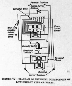
The low-energy characteristic of the relay has been obtained by substituting the low-energy CO overcurrent element for the standard CO overcurrent element. Thus the low-energy CR relay has overcurrent characteristics similar to those of the low-energy CO relay, and directional element characteristics similar to those of the standard CR relay.
Type CRA Relay
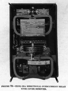
In cases where it is desired to have an indication of the current flowing in the circuit, the COA overcurrent element has been used in the CR relay in place of the standard CO element. This makes a compact, convenient arrangement serving the purpose of an ammeter without adding greatly to the expense of installation or detracting at all from the operating characteristics of the relay.
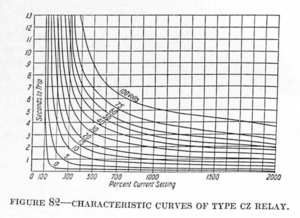
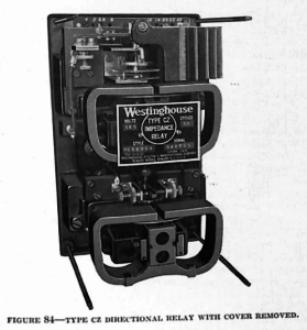
The Type CZ Impedance (Distance) Relay
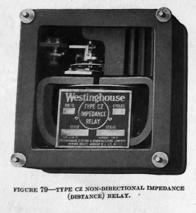
On large complicated transmission systems the method of sectionalizing by means of overcurrent and directional relays is often difficult to apply and sometimes even impossible. This is due to the necessity of employing such a large number of relays that it is impossible to keep the timing sequence within safe limits. At times it is impossible to secure proper discrimination at all, especially in the case of a complicated loop which is fed at several points, and where the points of feed change with load conditions. The Westinghouse Company has recently developed a relay which overcomes all such difficulties experienced on large and complicated systems. Its application does not supplant that of the standard CO and CR relays, but makes protection possible where otherwise it would be difficult or even impossible. The only requisite is that, with a short at the far end of the line, the impedance drop in the line should be at least 3.0% of the normal voltage—that is, the line must be of sufficient length to give this drop.
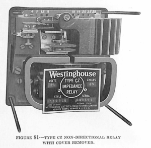
The CZ relay consists of an overcurrent element and a voltage element. The overcurrent element is similar to that of the CO relay. The special feature of this relay is the construction of the voltage element. The voltage element is so constructed that its action in relation to the closing of the relay contacts depends on the distance the relay is away from the fault. In other words, the voltage element acts in opposition to the overcurrent element, and when the relay is a considerable distance from the fault, the voltage on the element is comparatively high, thus lengthening the time required for the relay to close its contacts. On the other hand; the relays near the fault will have a very low voltage imposed on the voltage element, thus causing the relay to operate in much less time, due to less opposition being offered to the action of the overload element by the voltage element. Thus the relay that is nearest to the fault operates first, and at no time does the time exceed 0.75 to 1.0 second.
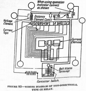
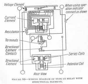
For some applications it is necessary to restrain the relay from operating unless the power is flowing in a given direction. To fill such needs a directional element similar to that of the CR relay is added to the CZ relay.
Type CA Ratio Differential Relay
The type CA ratio differential relay, Fig. 86, is a current-operated induction relay, similar in appearance to the type CO relay. As the name implies, it operates differentially, but it differs from the relays usually used in that the tripping current varies with the load. The current required to trip the relay increases in proportion to the line current instead of remaining constant for all load conditions.

This feature of the relay provides against faulty tripping due to a combination of “through” short circuits and variations of current transformer ratio, and allows the relay to be set for close protection at normal loads. Other methods of differential protection generally act on a difference of two currents, so that a slight difference in current transformer ratios, increased by heavy loads or by “through” short circuits, is often sufficient to cause enough circulating current to operate the relay. The CA relay is designed to avoid this trouble, and will trip out generators and motors on a trouble current as low as 2.5% of the line current, without danger of tripping the out on system troubles.

For protection of star-delta transformer banks, Scott connected banks, or in any case where the currents in the circuits to be balanced are unequal, the relay is provided with taps, so that balancing auto transformers are unnecessary. A saving in expense and in switch-board space is made possible by the provision of these taps. This relay is less sensitive than that used for generator protection.
In order to get the ratio feature of the relay, both of the secondary currents to be balanced, as well as the differential current, are used in the relay. A field proportional to the sum of the currents reacts with a field proportional to their difference, and the resultant field acts to produce rotation. The quadrature flux is supplied to the upper poles by transformer windings on each of the lower poles, as shown in the wiring diagram, Fig. 88.
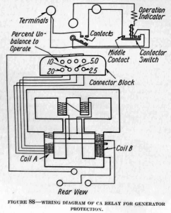
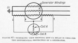
Fig. 87 shows schematically the connections of the CA relay for the protection of a generator. The arrows show the relative instantaneous directions of current flow under normal conditions. If the currents supplied by each transformer are equal, there will be no current flow in Coil A. If the current transformers supply unequal currents, the difference flows through coil A. The direction of current in coil A with respect to coil B does not affect the tripping direction of the relay.
The flux produced by coil B tends to hold the relay open, and that due to coil A tends to trip the relay. As the line currents increase, the torque holding the relay open increases, and more torque (and consequently more current) is required to close it.
The relay for generator protection is provided with a tapped “difference coil” winding (coil A, Fig. 87), so that the sensitivity may be varied readily. Fig. 88 shows the way the taps are brought out.
On the transformer relay the conditions are very similar, except that both the “sum coil” and the “difference coil” windings are tapped, in order to compensate for the effect of unbalanced currents. The sensitivity cannot be varied on this relay.
The energy required to operate the relays, particularly the transformer relay, is very small. This, combined with the fact that the operating current increases in proportion to the line currents, makes the relays very adaptable to conditions requiring the use of bushing-type current transformers.
When greater sensitivity is required, as in the case of the generator relay, the burden of the relay is somewhat greater, but under these conditions the current transformers used are of higher grade, and the load is well within the capacity of the current transformers.
The relay is very rugged, there are no adjustments to get out of order, and no delicate mechanical parts to give trouble. The contacts are set well out in front, where they can be seen through the glass cover, and where they are easily accessible for adjustments or repair. All the relays are provided with two trip circuits and with an operation indicator and contactor switch, as in the CO relay.
Type CB Overcurrent Relays
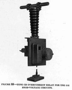
The cost of the current transformers used with relays often forms a considerable part of the entire cost. Where the current transformers must be connected to high-voltage circuits, they must be insulated for the high voltages; and their cost is high. The CB relay has been designed for use on high-voltage installations. It is a combination of the CO overcurrent relay and the BT transfer relay with the addition of a special contactor switch. A standard transformer is used without regard to insulation for the high-voltage line, and the CO relay element is connected in the usual manner.
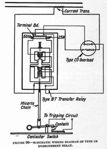
The CO and BT relays, however, with the current transformer, are mounted on a slate base which is mounted on an insulator. The contactor switch is separate from this assembly and is connected to the BT relay by means of a micarta chain. Thus the tripping circuit is insulated from the high-voltage circuit which is to be protected. When the CO relay contacts close they serve to operate the BT transfer relay. This relay, in turn, by means of the micarta chain, closes the tripping-circuit contactor switch. The operating characteristics of the CB relay are the same as those of the standard CO relay.
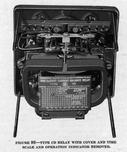
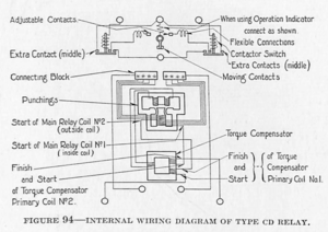
Type CD Selective-Differential Relay
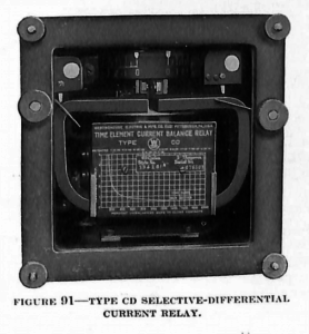
Balanced-current protection is very often desired where two or more similar transmission lines are used to connect two stations or two different points in a system. Balance-current protection on such lines means that each line normally carries approximately the same current, and if this condition does not exist the line carrying the greatest current must be in fault. The CD relay furnishes a simple method of securing such protection. It avoids the necessity for any special apparatus, such as split conductor cable, and as it operates on current alone, potential connections, or potential transformers are not required.
The relay operates on the induction principle and is in reality two overload elements so located that they act in opposition upon a common disc through a common magnetic circuit. Each element is connected separately to its own current transformer and to corresponding phases of the two lines that are to be protected. These two elements are electrically opposed, and under conditions of balanced line load, which will give approximately the same current in each element, the fluxes in the magnetic circuit of the relay are equal and opposite, giving a resultant zero torque in the relay disc. When a fault occurs in either line, however, the current in that line will become greater and the unbalance will cause the relay to operate, tripping out the line in which the greater current is flowing.
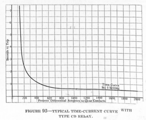
The CD relay has inverse-time characteristics and also a definite-minimum time of operation with excessive overcurrent. The inherent characteristics of the relay are such that when one line of a pair is tripped out double the normal current is required in the other line before it will be tripped out, thus making it possible for one of a pair of protected lines to be open and the other line to carry its load without interference from the relay. Any number of lines may be balanced against one another, but the tripping out of certain lines in a group will necessarily destroy the balance connection between the remaining lines.
The CD relay has the same current adjustment and time adjustment as that of the CO relay. The time adjustment is, however, seldom of importance, inasmuch as the relays usually are desired to operate almost instantaneously.
Type CW Power Relay
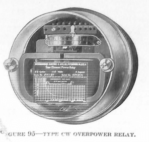
In many instances a motor is so connected to its load that under certain conditions the load may drive the motor, causing it to act as a generator. A mine hoist driven by an induction motor is a good example of such an installation. In such cases it is sometimes necessary to provide some sort of protection to insure against having the motor return too much power to the line when it is being driven as a generator. The CW power relay serves this purpose. It is also often used to prevent undesirable or excessive interchange of power between parts of a system, as in the case of a small plant connected in parallel with a larger plant where some means must be provided to prevent the small plant from being subjected to the entire load of the system, should the larger plant be suddenly disconnected.
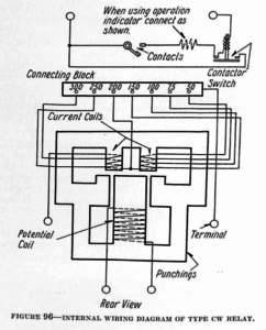
The CW relay is essentially a contact-making watt-meter. It operates on the induction principle and is similar to the CO relay, except that it requires both current and potential connections. It closes its contacts in but one direction and only after a predetermined time, when a predetermined quantity of power is flowing in a predetermined direction, which direction may be either the normal or the reverse, according to the way the relay is connected.
The relay has a standard time adjustment and also taps for changing the wattage values necessary to trip the relay.
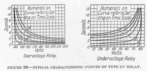
Type CV Voltage Relay
The CV relay is designed for general use when it is desired to have circuits or apparatus protected against voltage changes of any predetermined value. It operates to close a circuit either for the purpose of disconnecting the apparatus or of actuating a signal. The time-delay characteristic of the relay is used also in many applications where a timing-device is desired. In these applications the relay is used to close a circuit after a predetermined interval when the relay winding is energized.
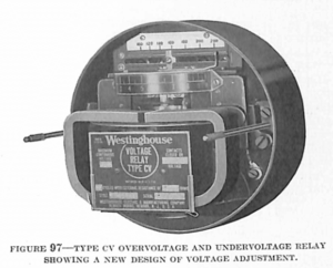
This relay is similar in appearance to the CO relay and operates on the same principle. The chief difference between the two types is that the CV relay operates on voltage, whereas the CO relay operates on current. The latest design of the CV relay is provided with a voltage adjustment, by means of which the operating voltage can be adjusted over a wide range.
This adjustment, which is shown in Figure 97, consists of a slide-wire resistor connected in the upper pole circuit of the relay. The resistor is provided with a calibrated scale so that the relay can be readily set to close its contacts at the desired voltage value. The time adjustment of the relay is identical with that of the CO relay.
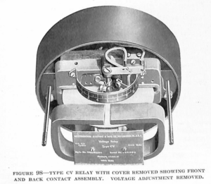
One form of the CV relay closes its contacts only when the voltage is raised to the operating-point or above, and another form closes its contacts only when the voltage is lowered to the operating point or below that value. These two forms are called overvoltage and undervoltage relays respectively. A third form is equipped with front and rear contacts, as shown in Figure 98. The front contacts close when the voltage is raised above the operating value and the rear contacts close when the voltage is lowered somewhat below that point.
When a relay having a long time-delay is desired, it is possible to supply a CV relay with a geared element similar to that of the low-energy CO relay. With this relay, a time-delay of as much as 60 seconds can be obtained.
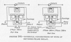
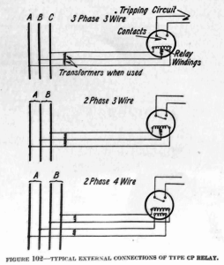
Type CP Reverse-Phase Relay
In many motor installations it is very essential that the direction of rotation of the motor always be in a given direction. This applies particularly to motors used in connection with control equipment or for motors used for operating elevators, pulleys, conveyors, cranes, machine tools, etc. The reversal of phase rotation in a polyphase system, caused by the reversal of two wires, although not of frequent occurrence, yet is liable to happen at any time when lines are being changed or repaired. Such a reversal of phase rotation means a reversal in the direction of rotation of all polyphase motors connected to the line. The CP reverse-phase relay serves to protect against such occurrences. It operates upon phase reversal or when any one phase of a polyphase circuit opens. In case of a phase reversal the relay may serve to disconnect the motors from the circuit. However, in case of one phase opening with polyphase motors operating on the system, the relay will not operate until the motors have been stopped, due to the fact that practically normal voltage is maintained on all phases by the motor. The relay will operate, however, as soon as the machines are stopped, thus preventing them from being again started.
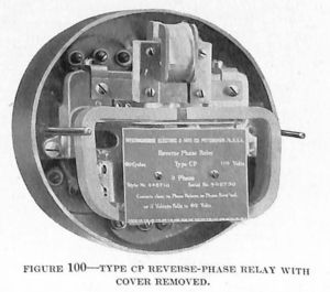
The CP relay operates on the induction principle, and has two windings, each of which is energized from a separate phase. The construction of the moving element is such that the disc is maintained in its normal position, with the contacts open, by the torque produced by the two windings. In case either winding is de-energized or the direction of current in one winding is reversed, the torque becomes zero or is reversed and the contacts are closed by the reversed torque or the action of a spring.
As the relay operates on the induction principle and the closing of the contacts depends on the rotation of the disc, a time-delay action is produced when the relay operates on low or unbalanced voltage. This time-delay action is a very important characteristic of the relay because it prevents the relay from tripping upon the occurrence of momentary voltage disturbances in the line to which the relay is connected.
Type CM Phase-Balance Current Relay
In installations where polyphase machinery, such as rotary converters and motors, is used, it is necessary to have some protective means available whereby the machine will be disconnected from the source of power in case of an unbalanced condition of the current flowing in the phases, or in case of a phase failure where the apparatus would be compelled to operate on single phase. This protection is necessary because a polyphase machine operating on a system with unbalanced phases, or on single phase, draws excessive current and may overheat. The CM phase-balance current relay is used to prevent such occurrences.
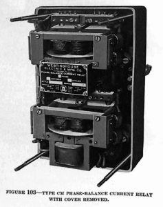
The CM relay operates on the induction principle and consists of four single-phase current elements mounted in a single case. The four elements are mounted in pairs, one pair being in the upper part of the case with its own disc, and the other pair in the lower part of the case with its disc. Each disc carries its own set of contacts, the two sets being connected in parallel in order that either disc may close the tripping circuit.
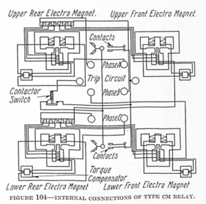
The two current elements in each pair are mounted on opposite sides of the disc and are so connected that the torque produced by one bucks that produced by the other. Therefore, when balanced conditions exist on the system there is no movement of the disc, but with an unbalanced or opened phase the balanced condition on the disc is destroyed and the tripping circuit is closed.
The relay has inverse and definite-minimum time characteristics, and it gives protection for each phase because all phases are represented in the winding. The value of the unbalanced current necessary to trip the relay may be adjusted by means of current taps as in the CO relay.
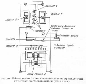
Type CQ Phase-Balance Relay
The CQ relay is designed to protect polyphase motors and rotary converters against running in case of an open phase, the reversal of phases, or in case of a three-phase unbalance such as is caused by a single-phase short circuit. This is necessary because operation with any of these conditions existing for considerable time will cause serious overheating. It is generally desirable to have machines disconnected from the line on as small an unbalanced condition as possible, and they should not operate on single-phase currents at all. With machines in isolated locations, however, it is sometimes desirable to have the machines kept on the line, running on single-phase or unbalanced current, if the load to be carried is not high enough to cause serious overheating or vibration in the machines. The CQ relay has current and time adjustments which make this operation possible wherever it is desired.
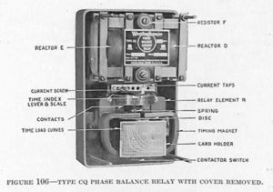
The relay operates on the induction principle, the operating element being very similar to that of the CO relay. The winding of this element is so connected that under normal conditions of operation no current is flowing in it. However, with any unbalanced condition, current will flow through the winding, operate the element and close the contact which may either actuate an alarm, or disconnect the protected machine from its source of power.
The CQ relay has an inverse-time characteristic. Its construction is such that it is extremely sensitive to small quantities of unbalanced current. The current necessary for operation may be adjusted, and the time required for the contact to close may also be changed. Its application is practically the same as that of the CM, but it is a more sensitive and a later-designed relay and should be used unless the CM is desired for some good reason.
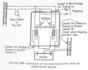
Type RF Frequency Relay
Sometimes it is desired to have the frequency of a circuit or system maintained at a given value or to have some means whereby a signal is given if the frequency varies from the given value. The RF frequency relay is designed to take care of such applications and may be used either to disconnect a circuit or to simply actuate a signal when the frequency changes above or below the normal value.
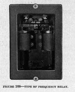
The relay consists of two coils operating on a balanced lever. The coils are connected across the same source, one with a reactance and the other with a resistance in series. As long as normal conditions exist, a balance is maintained on the lever and the contacts remain open, but a change in the frequency causes a change in the current flowing in the coil that has the reactance in series, whereas, the current flowing in the other and resistance coil remains practically the same. This condition causes an unbalance which closes the contacts and serves to perform the required operation. The relay can be made very sensitive and is adaptable to a variety of applications.
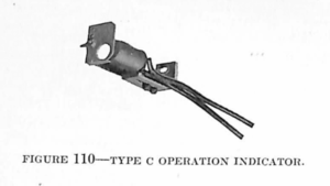
Type C Operation Indicator
In many installations where a number of relays are in service, a circuit-breaker may be tripped by one of several protective relays. As each relay affords protection against some special kind of fault in the line, it is highly desirable to know which relay has tripped the breaker in order to be able more easily to locate the trouble. As most protective relays reset automatically as soon as the circuit-breaker opens, it is difficult to determine which relay has operated without some auxiliary means. The operation indicator is a small coil serving to attract a semaphore into a visible position when the coil is energized. This operation indicator may be installed within the case of all the standard types of protective relays, and is connected in series with the tripping circuit. As soon as the relay closes its contacts, thereby closing the tripping circuit, the operation indicator is energized and attracts the indicator to the operated position. The indicator remains in this position until reset. The hand reset of the indicator is so arranged that it may be actuated without removing the cover of the relay.
Discover more from Valence Electrical Training Services
Subscribe to get the latest posts sent to your email.
Did you like this post?
You can share it with these links:
Read More Articles:
Direct-Current Relays from 1924 Silent Sentinels
Thank you for these articles. This is very helpful
Thank you for making this pamphlet available to relay testers and engineers. This is great information. One thing would have been very helpful, namely How to adjust the pick-up of the relay, for example we have many 3-phase CO relays that are shown in this instruction booklet (page 4, figure 60), but some of them need the minimum pick-up adjusted. The “watch” type of spring is soldered and does not seem to be adjustable. Are there any instructions on how to make this adjustment. This goes for the rest of the electro-mechanical relays as well, such as STD, SPD etc.
Thank you,
Vahan Bars
Thanks for the comment. You modify the spring tension by turning the sprocket under the spring. We don’t have plans to cover any E-M relays because the manuals are usually well written and there is 50 years of content about them already out there.
Good luck.
Thanks for your knowledge of Matt