Why Does My Open-Delta Connected Phasor Diagram Look Weird?
Meter tests on protected relays connected to open-delta connected PTs can be very confusing. I know I spent a LOT of time trying to figure out the values reported by my first open-delta connected relay during my first simple meter test. The voltage and current phasors were completely out of whack and didn’t seem to make any sense, especially when I was told to use an old-timey connection like this:
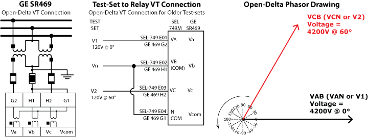
This connection is wrong on many levels, so we spend an entire section on the correct way to simulate open-delta voltages in the upcoming The Relay Testing Handbook: Simplified Motor Protection. Since this post is about the Amp measurements, we’ll keep the description brief here. Don’t use the connection above! That complexity was required for 20th century test-sets and relays. Use the simple rules for CT/PT connections described in the The Relay Testing Handbook: Principles and Practice and the How to Test Protective Relays Online Seminar:
- Replace each CT with a test-set current channel.
- Replace each in-use voltage signal with a voltage channel.
Modern Open-Delta Test-set to Protective Relay Connections You Should Be Using
If you follow these drawings, the voltage connections and injected voltages are much simpler.

The test-set generates the following open-delta connected phasor diagram that looks exactly the same as a wye-connected test-set and protective relay.
Unfortunately, that’s not the open-delta connected phasor diagram that the relay will report back to you.
This excerpt from The Relay Testing Handbook: Simplified Motor Testing will explain how an open-delta connected relay measures and reports Amps when connected to open-delta PTs. I hope it saves you the headaches it caused me when I was trying to figure it all out!
“Current Meter Test with Delta Voltages” Excerpt from The Relay Testing Handbook: Simplified Motor Testing
“…what happens to the current angles when you have Delta voltages? Will they be the same as a Wye voltage connection, or should they be different?
| Test-Set Channel | Prefault |
Relay Metering (GE SR469) |
Relay Metering (SEL-749M) |
|
| Magnitude | Angle | |||
| V1 Voltage | 69.28V | 0.00° | Vab = 4200V @ 0° | VAB = 4200V @ 0° |
| V2 Voltage | -120.00° | Vbc = 4200V @ 300° | VBC = 4200V @ -120° | |
| V3 Voltage | 120.00° | VCA = 4200V @ 120° | ||
| I1 Current | 1.000A | 0.00° | 50A @ ?° | 50A @ ?° |
| I2 Current | -120.00° | 50A @ ?° | 50A @ ?° | |
| I3 Current | 120.00° | 50A @ ?° | 50A @ ? | |
The answer depends on what the relay uses as a reference. A relay usually uses whatever is connected to Va-Vn as its reference. That’s why the phase angles in the previous “Current with Wye Voltages” section from the Acceptance Testing chapter match. The test-set is connected to the relay as shown in Figure 6-6 where V1 and VN of the test-set are connected to the Relay Va and Vn terminals. The test-set injects 0° from V1 to VN, and the relay uses that as a reference. If V1 and I1 are at 0°, the relay will report the angle as 0° because it is in phase with Va-Vn.
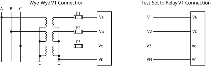
Figure 6-6: Test-Set Connection with Wye PTs
The Delta voltage connections are significantly different as shown in Figure 6-7. Notice that the neutral of the test-set is no longer connected to the neutral of the relay, and that there is a jumper between the Vb and Vn of the relay.
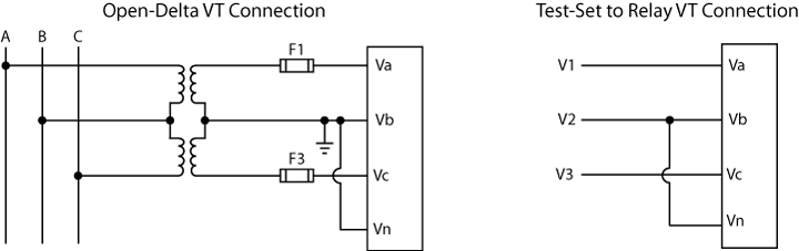
Figure 6-7: Modern Test-Set Connection with Delta PTs
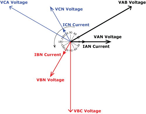
Figure 6-8 displays a phasor drawing showing the differences between Wye and Delta voltages with line currents in-phase with the Wye voltages. Notice the 30° phase shift between the VAN and VAB voltages?
Figure 6-8: Wye/Delta Voltages and Line Current Phasor Diagram
A Delta-connected relay doesn’t see the Wye voltages, so we’ll remove them in Figure 6-9, which is a good representation of what the test-set thinks is happening using Delta voltages and Wye currents.
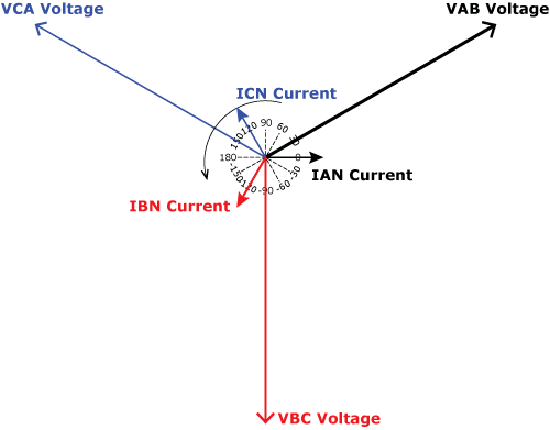
Figure 6-9: Delta Voltages and Line Current Phasor Diagram
The relay most likely uses whatever is connected to Va-Vn as its reference. If you follow those terminals back in Figure 6-7, you’ll find that they’re connected to V1 and V2 of your test-set, which is the same as VAB on the phasor diagram. Figure 6-10 shows what the relay will think the phasor diagram really is. Did you notice that everything has shifted by -30°?
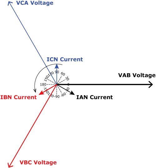
Figure 6-10: Delta Voltages and Line Current Relay Phasor Diagram
The relay sets the VAB voltage at 0°, and now the current is lagging by 30° as far as the relay metering is concerned, even though the P-N currents and voltages are technically “in-phase”. This can be confusing for relay testers unless they know how the relay determines angles. Always understand how the relay works before you test it.
The expected values in the relay with Delta voltages are shown in the following table.
| Test-Set Channel | Prefault |
Relay Metering (GE SR469) |
Relay Metering (SEL-749M) |
|
| Magnitude | Angle | |||
| V1 Voltage | 69.28V | 0.00° | Vab = 4200V @ 0° | VAB = 4200V @ 0° |
| V2 Voltage | -120.00° | Vbc = 4200V @ 300° | VBC = 4200V @ -120° | |
| V3 Voltage | 120.00° | VCA = 4200V @ 120° | ||
| I1 Current | 1.000A | 0.00° | 50A @ 30° | 50A @ -30° |
| I2 Current | -120.00° | 50A @ 150° | 50A @ -150° | |
| I3 Current | 120.00° | 50A @ 270° | 50A @ 90° | |
What happens if the IA current is the reference inside the relay?
The relay phasor diagram reverts back to Figure 6-9 to make the Ian Current 0° and the relay will report the following metering results:
| Test-Set Channel | Prefault |
Relay Metering (GE SR469) |
Relay Metering (SEL-749M) |
|
| Magnitude | Angle | |||
| A-Phase Voltage | 69.28V | 0.00° | Vab = 4200V @ 330° | VAB = 4200V @ 30° |
| B-Phase Voltage | -120.00° | Vbc = 4200V @ 90° | VBC = 4200V @ -90° | |
| C-Phase Voltage | 120.00° | VCA = 4200V @ 150° | ||
| A-Phase Current | 1.000A | 0.00° | 50A @ 0° | 50A @ 0° |
| B-Phase Current | -120.00° | 50A @ 120° | 50A @ -120° | |
| C-Phase Current | 120.00° | 50A @ 240° | 50A @ 120° | |
Now that you understand how currents and voltages relate in an Open-Delta connected relay, take another look at the old-timey connection from Figure 6-5 (shown below):
What will the relay see if we add normal current to the test plan as shown below?
| Test-Set Channel | Prefault |
Relay Metering (GE SR469) |
Relay Metering (SEL-749M) |
|
| Magnitude | Angle | |||
| V1 Voltage | 120V | 0.00° | Vab = 4200V @ 0° | VAB = 4200V @ 0° |
| V2 Voltage | 120V | 60.00° | Vbc = 4200V @ 300° | VBC = 4200V @ -120° |
| V3 Voltage | 0V | 0.00° | VCA = 4200V @ 120° | |
| I1 Current | 1.000A | 0.00° | 50A @ ??° | 50A @ ??° |
| I2 Current | -120.00° | 50A @ ??° | 50A @ ??° | |
| I3 Current | 120.00° | 50A @ ??° | 50A @ ??° | |
The relay uses whatever is connected to Va-Vn as its reference, so the relay will report the following information:
| Test-Set Channel | Prefault |
Relay Metering (GE SR469) |
Relay Metering (SEL-749M) |
|
| Magnitude | Angle | |||
| V1 Voltage | 120V | 0.00° | Vab = 4200V @ 0° | VAB = 4200V @ 0° |
| V2 Voltage | 120V | 60.00° | Vbc = 4200V @ 300° | VBC = 4200V @ -120° |
| V3 Voltage | 0V | 0.00° | VCA = 4200V @ 120° | |
| I1 Current | 1.000A | 0.00° | 50A @ 0° | 50A @ 0° |
| I2 Current | -120.00° | 50A @ 120° | 50A @ -120° | |
| I3 Current | 120.00° | 50A @ 240° | 50A @ 120° | |
Everything looks OK when we look at the numbers, but compare the phasors for our old-timey connection on the left-hand side of Figure 6-11 to the phasor diagram when we correctly simulated the phasors on the right-hand side of Figure 6-11. Do they look the same? They should if we’re doing our jobs correctly.
[one_half_first]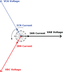
Old Open-Delta Connection[/one_half_first][one_half_last]
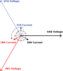
Power System Simulation[/one_half_last]
Figure 6-11: Open-Delta Voltage and Line Current Relay Phasor Diagram Comparison
Everything seems to be correct when the Vab voltage numbers are compared to the Ia currents, but the relay is actually measuring a LEADING current.
We can improve this connection by either remembering to lag our currents by 30° for every test, which isn’t practical because we usually modify the current angle when simulating faults. It would be better to alter the voltage angles instead, as shown in Figure 6-12, because the voltage angles in motor protection typically don’t change. Now we will read correct voltage and current angles during our meter test.
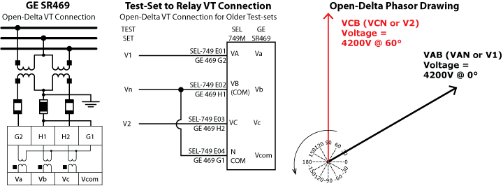
Figure 6-12: Old Open-Delta PT Connections with Correct Angles
| Test-Set Channel | Prefault |
Relay Metering (GE SR469) |
Relay Metering (SEL-749M) |
|
| Magnitude | Angle | |||
| V1 Voltage | 120V | 30.00° | Vab = 4200V @ 0° | VAB = 4200V @ 0° |
| V2 Voltage | 120V | 90.00° | Vbc = 4200V @ 300° | VBC = 4200V @ -120° |
| V3 Voltage | 0V | 0.00° | VCA = 4200V @ 120° | |
| I1 Current | 1.000A | 0.00° | 50A @ 30° | 50A @ -30° |
| I2 Current | -120.00° | 50A @ 150° | 50A @ -150° | |
| I3 Current | 120.00° | 50A @ 270° | 50A @ 90° | |
The metering results from the modern Delta connection are shown below. Do you see they are identical? You can use either connection to test the relay, but I prefer the modern connection because it requires less thought on my part.
| Test-Set Channel | Prefault |
Relay Metering (GE SR469) |
Relay Metering (SEL-749M) |
|
| Magnitude | Angle | |||
| V1 Voltage | 69.28V | 0.00° | Vab = 4200V @ 0° | VAB = 4200V @ 0° |
| V2 Voltage | -120.00° | Vbc = 4200V @ 300° | VBC = 4200V @ -120° | |
| V3 Voltage | 120.00° | VCA = 4200V @ 120° | ||
| I1 Current | 1.000A | 0.00° | 50A @ 30° | 50A @ -30° |
| I2 Current | -120.00° | 50A @ 150° | 50A @ -150° | |
| I3 Current | 120.00° | 50A @ 270° | 50A @ 90° | |
This can all get confusing! Especially when you are looking at phase angles. It is always important to understand what your relay uses as a reference if you want to perform a proper meter test.”
Conclusion
I hope this excerpt saved you from the headaches I had trying to figure out the open-delta connected phasor diagrams the first time I tested an open-delta connected relay.
If you aren’t already getting our free technical articles in your inbox, sign up on the right to get all of the free extras we send out every two weeks, as well as occasional promotions.
Get The Relay Testing Handbook Today!
Still confused? I came across this explanation from a different perspective that might help: https://www.electricalpereview.com/open-delta-transformer-connection/
Discover more from Valence Electrical Training Services
Subscribe to get the latest posts sent to your email.
Did you like this post?
You can share it with these links:
Read More Articles:
How to Perform Dynamic Relay Testing on Digital Relays
Emails are great!! Thank you.
Thanks!
I found attempting to explain it to others to be the most challenging. Thank you Chris
These are great tools for understanding
Thanks!
Simply great >>>> thanks.
Very good information, thanks Chris
What helped me the most was a phasor diagram depicting the power system wye voltage with standard sequence (VAN@0, VBN@-120, VCN@120). When those voltages are applied to the open delta windings the common point shifts to B phase, so the new diagram (with the tip of VBN as common) results in VAB@30 and VCB@90.
Don’t get in the habit of thinking about an open-delta that way for relay testing. It leads to the dark side and caveman testing. :)