Methods of Applying Relays to Circuit-Breakers from Silent Sentinels 1924
Silent Sentinels 1924 Excerpt #2
This excerpt from the 1924 version of Silent Sentinels discusses how electrical engineers were applying relays to circuit-breakers in 1924. This is the 2nd in the series. Follow these links to learn more about this series and the 1924 version of Silent Sentinels.
1 – Alternating-Current Circuit-Breakers
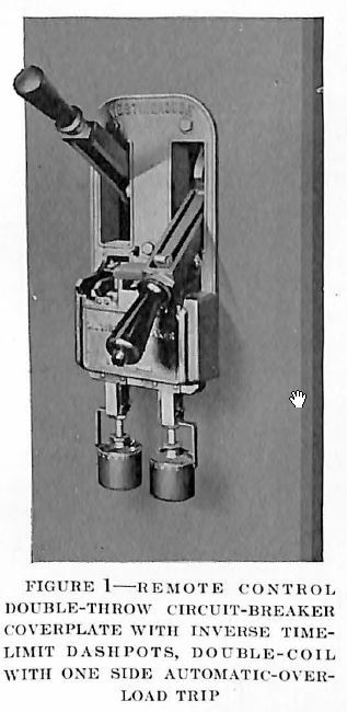
Automatic Characteristics—Small alternating-current circuit-breakers often have automatic characteristics built into them, in which case relays are not required. These self-contained automatic characteristics are simple and usually consist of plain overcurrent trip coils arranged so that they can be adjusted to operate on any desired current value, a common range being 4 to 8 or 12 amperes. Sometimes these trip coils are equipped with simple time-limit devices such as dash pots, which are not very accurate, but which are reliable and, because of their simplicity, are in common use. Breakers, so equipped, are used without relays on small feeders where there is little need for the more highly developed, discriminating action of the relay.
Sometimes breakers are equipped with low-volt-age release coils, but from the consideration of continuity of service this is not desirable because the circuit-breakers so equipped will be tripped open whenever there is line trouble in the vicinity, even it the disabled line is automatically cleared from the rest of the system.
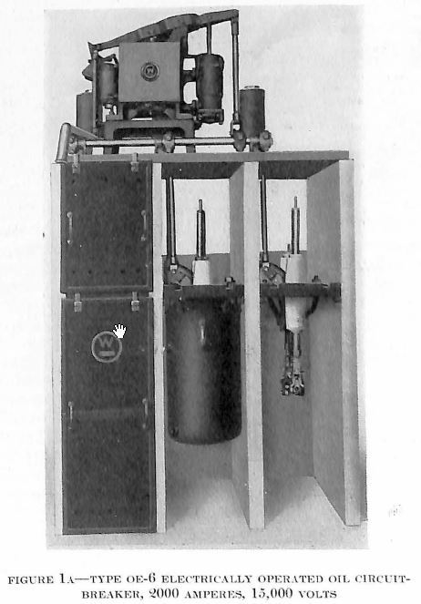
Shunt Tripping-Where automatic circuit-breakers in themselves are not suitable, it is necessary to use relays. The simplest method of doing this is to place a direct-current coil on the breaker and connect the protective relays so that their contacts will close, the tripping circuit whenever it is desired to automatically open the breakers. This is known as “shunt” tripping. Most large circuit-breakers are now electrically operated, and the trip coil to which the relays are connected is the same trip coil as that used during non-automatic operation of the breakers. Sometimes, however, the breaker is closed by hand, and supplied with a trip coil for automatic opening.
The question arises as to where to obtain power for tripping purposes. In the past it has been common practice to use six-volt storage batteries for this purpose, but trouble is often encountered with such a low voltage, because of bad connections or poor contacts in the circuit. Twelve-volt batteries give less trouble of this sort, and are often used, but it is recommended that twenty-four volt batteries be given preference. A large part of the expense of such an installation consists of the cost of the device necessary to keep the battery charged, and, therefore, the extra expense of increasing the voltage from six volts to twenty-four volts is not a large percentage increase. Automobile batteries are probably the cheapest for this purpose. These can be obtained readily, but are said to have the disadvantage of losing their charge more rapidly than do some other types. Where the battery can be charged only at rare intervals it is suggested that special batteries of the type used in railway signaling be installed. Sometimes the battery can be arranged so that it will be kept charged by a trickle charge, and this practice is recommended. It is important to install a type of battery which will not freeze in severe weather and it is important also to test each circuit occasionally to see that it is in working order.
In most of the present-day generating stations and larger sub-stations, a 125-volt direct-current source is used for all control work. This source is usually maintained by a motor-generator set having a storage battery floating on the line in order to insure against any possible interruption. Most standard circuit-breakers can be equipped with trip coils for any of the mentioned voltages.
Alternating-Current Shunt Tripping—Sometimes trip coils have been operated by alternating-current voltage but the trouble with such an arrangement is that their source of power is usually so closely associated with the circuits to be protected, that in case of a heavy short circuit the voltage will be too low to operate the trip coil, and thus the breaker will fail to open at the time when its proper operation is most necessary.
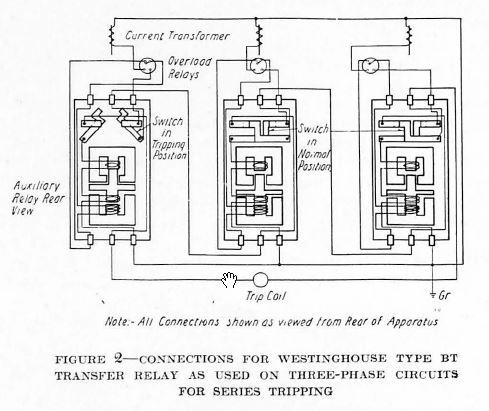
Series Tripping—A common method of tripping, known as series tripping, is to use the ordinary alternating-current trip coil connected in series with the current transformer secondary, and to normally short circuit this trip coil by means of contacts on the relay. When the relay operates it opens these contacts, and allows the current from the current transformers to flow through the trip coil and thus operate the breaker. There are several objections to this method, one of them being that some protective relays are intended to operate when the current flowing through the trip coil is comparatively small and, therefore, insufficient to operate the breaker. Another objection to this arrangement is that heavy contacts are required and it is difficult to apply these contacts to relays having the accuracy required of present-day service, and having the other necessary requirements, such as a small burden on the current transformers. It usually is demanded that the trip coil shall be capable of operating when the current is at least as low as five amperes, which requires that it shall have an impedance of one ohm or more. On the other hand, a short circuit may be so heavy that the current in the trip roil is limited only by the ability of the current transformer to supply it. Such short-circuit values through the trip coil may amount to 100 or 200 or even 300 amperes. It is, therefore, necessary for the relay contacts to be able to carry five amperes continuously without over-heating and at the same time be able to successfully withstand the opening of a circuit of approximately 300 amperes at 300 volts. Needless to say, no satisfactory relay has yet been designed for this service. Where conditions are such that tripping by means of the current transformers is demanded, the type BT transfer relay can be used, provided reasonable attention is given to keeping its contacts in proper operating condition.
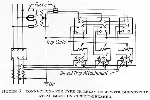
Certain types of circuit-breakers are furnished with a “direct-trip” attachment, an excellent device even though the name is somewhat misleading. Such breakers are tripped by current from the current transformers, but the arrangement is such that sensitive relays can easily control the operation of the trip coils without injury to their contacts. This “direct-trip” attachment operates on the same principle as does the type BT transfer relay, which is itself, described farther on in this book.
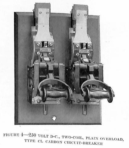
2 – Direct-Current Circuit-Breakers
Direct-current circuit-breakers usually have automatic features included in their structure. Overload trip coils are customary and often they are equipped with inverse-time-limit devices. Underload release coils have been used in a few rare cases and low-voltage release coils are quite common. Where relays are used to open direct-current breakers the conditions are sometimes such that tripping can be done by the low-voltage release coil. This can be effected either by connecting the relay contacts in series with the voltage release coil, so that the relay opens the circuit, or by connecting the relay contacts around the trip coil, so that they short circuit it when the relay operates. When the contacts short circuit the low-voltage release it is necessary to use a resistance in series with the coil so that when the relay short circuits the coil it does not short circuit the line. This same method can also be applied to any alternating-current circuit-breaker equipped with a low-voltage release coil.
Another method of opening a direct-current breaker is by means of a shunt trip coil deriving its power from the direct-current bus-bars. Usually such breakers are hand-operated, but occasionally they are electrically-operated. The recent increase in the use of automatic control equipment has called for new designs in circuit-breakers that are both opened and closed electrically. These are particularly useful on service restoring equipment or, as they are sometimes called, automatic reclosing breakers.
3 – Control Circuits
Circuit-Opening vs. Circuit-Closing Tripping – Occasionally the question arises as to the relative merits of circuit-opening and circuit-closing methods of connecting relays into the circuit. However, where a separate tripping circuit is used, it is the universal practice to use circuit-closing relays to protect against short circuits. It is true that the method of control used in industrial work, particularly elevator control, makes use of circuits that are normally closed, so that any failure in the circuit will shut down the apparatus. However, when the service is to be protected, as distinguished from the apparatus, it is considered the better policy to use control circuits which are normally de-energized. In the case of automatic operation of stations, the question is largely one of convenience, and both methods are used.
Supervision of Control Circuit – Closely allied with this question is the one of supervising the control circuit so that the operator can be certain that the circuit is always in an operative condition. This supervision can easily be accomplished by the use of a supervisory lamp which is connected in the control circuit in such a way that a small current continuously flows through it and through the entire tripping circuit, including the trip coil. In case of a failure anywhere in the tripping circuit, the lamp will, of course, be extinguished. The control circuit can be so arranged that the red indicating lamp, which normally indicates that the circuit-breaker is dosed, will also supervise the tripping circuit.
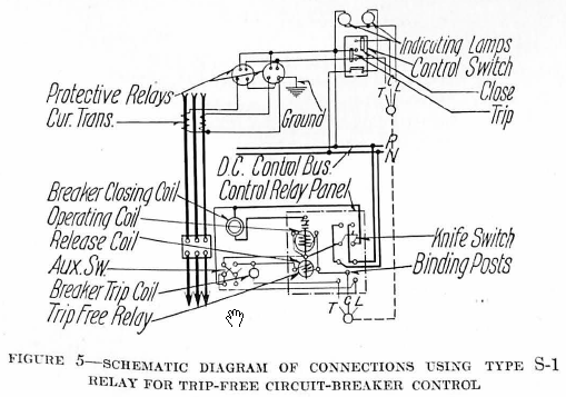
Trip-Free Breaker Control – Hand-operated, automatic circuit-breakers for both alternating current and direct current are almost invariably “full automatic,” that is the operator cannot hold them closed on a short circuit. When a circuit-breaker is operated by protective relays it is usually considered desirable to retain this characteristic and, therefore, it is customary to use what is known as a “trip-free auxiliary relay” in the control circuit, so that if the operator closes the breaker on a short circuit and the relay trips it open, it will not reclose, no matter how long the control switch may be held in the closing position. The trip-free relay locks out the closing circuit until the control switch is released.
Multiple Control Circuits – Sometimes it is desirable to trip several breakers simultaneously from one relay. This can be done by connecting their trip coils permanently together, but it is objectionable when it is also desired to operate them independently by hand. The usual requirements are to have the circuit-breakers operate independently under normal conditions and operate simultaneously only by the relays. It is, therefore, necessary to keep the trip coils separated when they are to be manipulated by hand. One way of accomplishing this is to interpose an auxiliary multi-contact relay between the Protective relay and the group of circuit-breakers. This is sometimes considered objectionable because it introduces another piece of apparatus into the protective scheme.
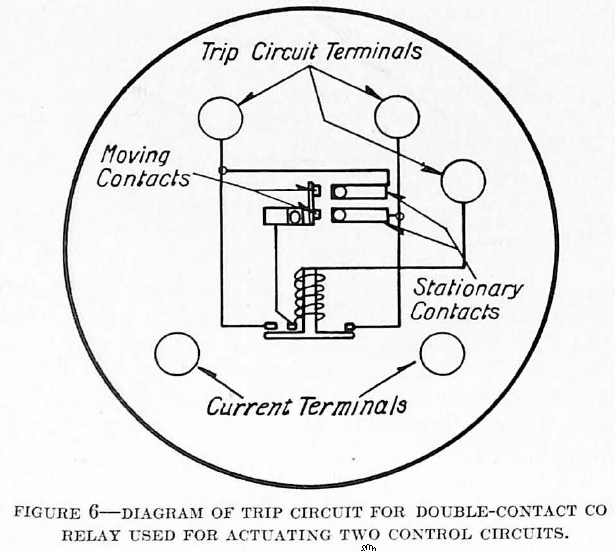
Another method of accomplishing the same result, where it is desired to operate only two breakers simultaneously, is to use protective relays equipped with double contacts. These contacts are arranged to keep the two tripping circuits separate and to close them simultaneously.
Another method quite commonly used is to arrange the tripping circuits so that normally all of the trip coils are connected together so that a single relay can trip all the breakers. A special contact on the control switches is so arranged that whenever one of the breakers is operated by hand, the special contact on the control switch will first break the tie between the various circuits.
Time Required to Open a Breaker
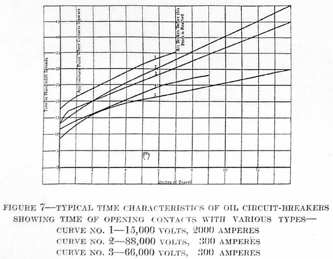
Where a time-limit is depended on to discriminate between various relays, it is important to consider the time required for the operation of the circuit-breakers themselves. Although the size of the circuit-breaker has much to do with its speed of operation, its mechanical adjustment is also of importance. Much of the time required for operation is consumed in energizing the trip coil and in overcoming the inertia of the moving parts so that after the contacts have once separated the time required for the breaker to complete its travel is not long. Small circuit-breakers, equipped with instantaneous automatic overcurrent trip coils, can be made to operate very rapidly, because upon the occurrence of a short circuit the trip coils will release the latch quickly, sometimes within a cycle.
The characteristic curves (Fig. 7) show the time required to open several modern types of circuit-breakers.
Signals
An audible signal of some kind is usually provided to sound whenever a breaker is tripped automatically. A common method of accomplishing this is to provide a separate bell bus on one side of the control circuit and interpose a series signal relay between this bus and the source of supply.
The normal hand-operation of the breakers is done from the main control bus, so that no alarm is given, but whenever a primary relay operates it energizes the bell bus and the signal relay. The operation of the signal relay usually causes a bell to ring continuously until the relay is tripped. A type OL relay which can be manually reset by a pull button on the relay cover is recommended for this purpose. If the signal relay is to be mounted in the rear of the panel the type OX should be used. This type is electrically reset by means of a push button conveniently located on the front of the panel.
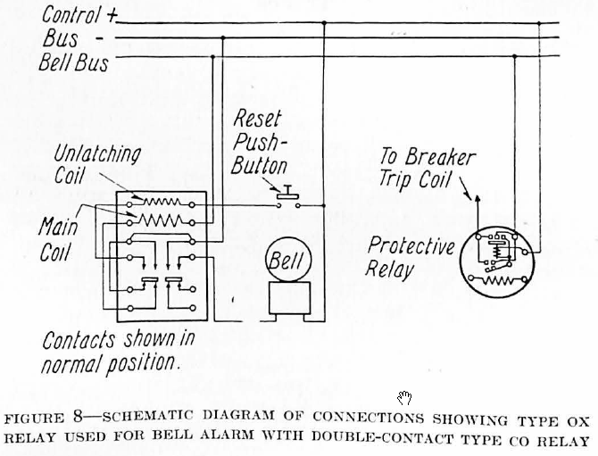
The objection often arises that this relay scheme interposes an additional hazard in the tripping circuit, although its operating coil is wound with wire of such size that it is not liable to become accidentally open-circuited. Because of this objection, it is becoming the common practice to use an alarm relay having a shunt coil operated in parallel with the trip coil of the circuit-breaker. In order that one signal relay may be operated by any number of protective relays, it is necessary to have a separate signal contact on the protective relay, as shown in the diagram, Fig. 8.
Discover more from Valence Electrical Training Services
Subscribe to get the latest posts sent to your email.
Did you like this post?
You can share it with these links:
Read More Articles:
Understanding Distance Protection (21) Video
You must be getting older my young friend….looking backwards is a sign of wisdom and maturity….I can send you a paper I did on the history of breakers on request….
Thanks John. I can always use more content if you want to post it under your name
Anyone can start a post at the Add Your Post to Techtalk link. https://relaytraining.mystagingwebsite.com/become-techtalk-contributor/