Typical Relay Application from Silent Sentinels 1924
Silent Sentinels 1924 Excerpt #11
This excerpt from the 1924 version of Silent Sentinels discusses typical relay applications used in the early days of electrical systems. Are they much different than the relay applications used today? This is the 11th in the series. Follow these links to learn more about this series and the 1924 version of Silent Sentinels.
Typical Relay Application
When it is desired to relay a power transmission system there are many factors which enter into the problem, all of which must be given consideration. In most systems, so many complications are present that it is almost impossible to secure an ideal application of relay protection. However, in most cases it is possible to arrange the relay settings so that certain lines, in case of a fault, may be disconnected without disturbing the service, and the disconnecting of these lines leaves conditions such that ideal selective action is secured on the rest of the system. Where distance between stations is great enough to give the necessary 3 per cent. drop, and it is convenient to use the type CZ relay, these complications may be eliminated.
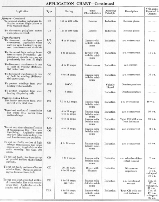
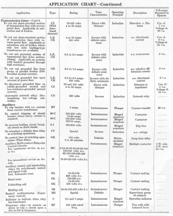
Fig. 64 shows a schematic sketch of a typical network system which will be used as a basis for illustrating one method of making an initial relay application. Upon analysis, the network is found to be really a loop system, with tie line No. VIII connecting Parsons and Kubiac substations, and No. IX connecting the generating station with the Kubiac sub. This loop, without these ties, connects seven substations with the generating station. Either the CO-CR or the CZ relay scheme will be the typical one to use; therefore the CO-CR scheme will be chosen, with the CZ scheme as an alternative. Standard CO overcurrent relays are, therefore, allotted to each outgoing line (Nos. I, II, IX, XI) at the generating station, and standard CR directional overcurrent relays on each line of the loop at each substation. The type CR relays are connected so that the directional element contacts will close only when power is flowing away from the substation bus bars. It should be remembered throughout this discussion that excess current flowing in this direction is necessary to complete the tripping circuit.
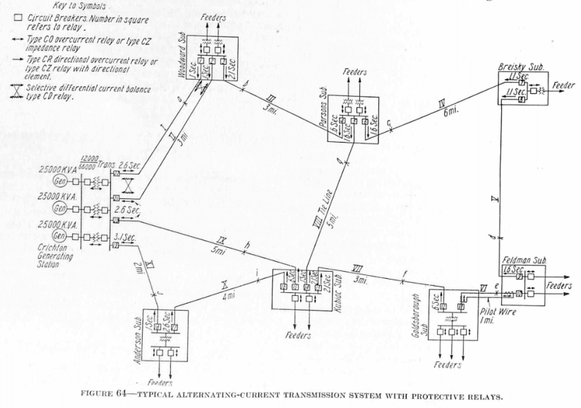
After assigning relays to the various lines, the next problem is to assign time settings to the relays and then check out to determine if the proper time-intervals necessary for selective action can be allowed without having excessive time-settings on any of the relays. A five-tenths second interval between relay settings is commonly used in present-day practice, this value allowing 0.35 second for the breaker to open after the trip circuit has been made, and 0.15 second margin. The maximum allowable setting, of course, depends on the system, but 3.1 seconds is considered the highest time-setting which it is safe to use, and a maximum of 2.6 seconds is adhered to wherever possible.
Referring to the system in question, there are seven substations in the loop which would require a maximum time-setting of 3.6 seconds for the relays at the generating station. This value is rather high, therefore some way must be found to lower it. When checking the distance between stations, it is found that line VI is comparatively short, hence a pilot wire scheme may be used to protect this section. That makes one less section to be counted in adding the successive time-intervals, but 3.1 seconds is still higher than is desirable. Trying to find some means of eliminating one more section, it is observed that the Anderson sub might be eliminated from the loop for the first trial application, making tie line No. IX a part of the loop. This will make it possible to obtain the proper intervals between successive relays, with a maximum setting of approximately 2.6 seconds.
Definite time-settings may now be assigned to the successive relays in the following manner: Beginning at the Woodward sub, the CR relays Nos. 1 and 2 on lines I and II, set to trip with power flowing from the sub to the generating station, may be set to trip almost instantly, because a fault on line No. I or. II is the only circumstance to cause excess current to flow in this direction, and therefore the relays may be set to clear as soon as possible. It is customary to make this setting 0.1 second. Going on to the next sub (Parsons), we find that relay 4 on line No. III at this sub is set to trip with power flow in the same direction, namely away from the bus bars towards Woodward sub. This relay must, accordingly, be given a higher time-setting because a fault on line I or II will draw current through relay 4 and, therefore, it is essential to have relay 1 trip first. A definite setting of 0.6 second is, therefore, assigned to it. In like manner each successive relay connected to trip with the power flow in this direction is given a setting of 0.5 second higher than the next preceding one which leads to a setting of 2.6 seconds on relay 20 at the generating station. Relay No. 11 at Goldsborough sub may be ignored, because it can be set to trip almost instantly when a fault occurs in line VI, but a fault on any other part of the system will not affect it.
A similar procedure is followed out for the relays set to trip with the power flow in the other direction, or clockwise, as it might be considered. Beginning at Kubiac sub, relay 15 is assigned 0.1 second setting; relay 12, 0.6 second; relay 8, 1.1 second and so on, until relays 21 and 22 at the generating station are reached.
The next problem which must be met and solved is the time-setting for relays 5 and 14 on line VIII and relays 16, 17, 18, 19 on lines X and XI. No definite rule can be followed for making the settings on relays 5 and 14. Very often the relays on a tie line are set to trip in a short time whenever excess current flows, because this action makes the relay operation on the rest of the system simpler, and does not injure the service. In this case, however, by assigning a setting of 1.6 seconds to relay 5, and 2.1 seconds on relay 14, comparatively good protection is secured for line VIII, and neither relay will trip with a fault elsewhere on the system except in one or two cases, as will be shown later.
The lines X and XI may be considered as completing the loop from substation Kubiac rather than line IX, and the settings assigned to fit-in with the rest of the loop as already described.
A check can now be made, assuming a fault in each line in turn, and then determining whether the proper relay operation will take place. Assuming a fault on line I at a, current will flow to the fault from the generator station and from Woodward sub. Thus relay I will clear within 0.1 second, cutting off all flow from that direction, and relay 22 will clear within 2.6 seconds. Assuming a fault at b on line III, current will flow in from both directions, tending to trip relays 7 at Breisky, 14 at Kubiac and 21 and 22, in addition to 3 and 4, at the immediate ends of the line. Relay 3 will beat 22 and 21 out, thus clearing the fault in that direction, and relay 4 will trip in 0.6 second, which is a shorter period than that of any of the others that will be likely to trip. Assuming faults at c on line IV, d on V, g on VIII, e on line VI, h on line IX, j on line XI and on line X, the action may be checked out in the same way. Assuming a fault on line VII at f, we find that current may be drawn from both directions; that coming from sub Kubiac, being possibly drawn from lines VIII, IX and X. In case enough current is drawn from line VIII to give relay 5 its definite minimum time of tripping, it may trip before relay 13 clears. However, relay 13 will trip before any other relays in the system, therefore the opening of the tie line is not serious. There is also a possibility of setting the current taps on relay 5 so that it will be operating on the inverse part of the curve under such a condition and thus increase its time of tripping to the extent that relay 13 will trip first.
If it is desired, and an analysis of short-circuit current values shows that sufficient unbalance will exist between lines I and II with a fault in either one, additional current balance CD relays may be installed at each end. These will provide a means for clearing either line almost instantly when they are both in service and one develops a fault.
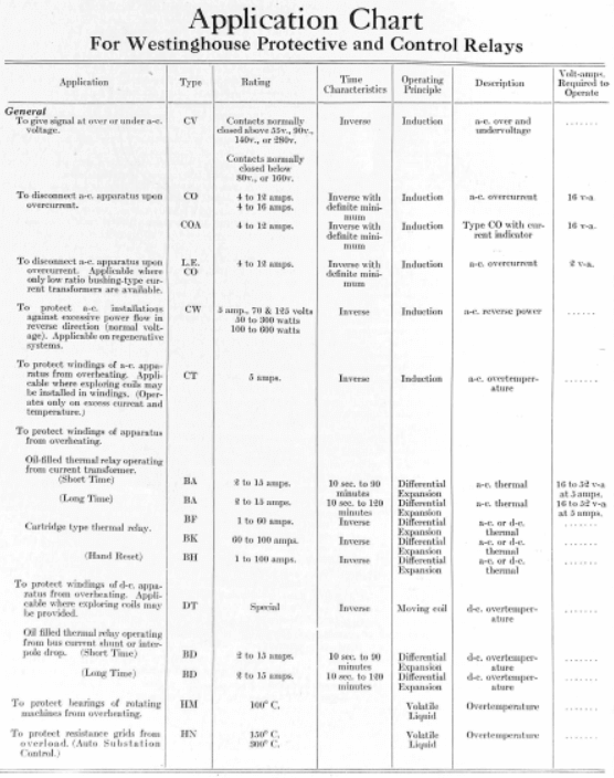
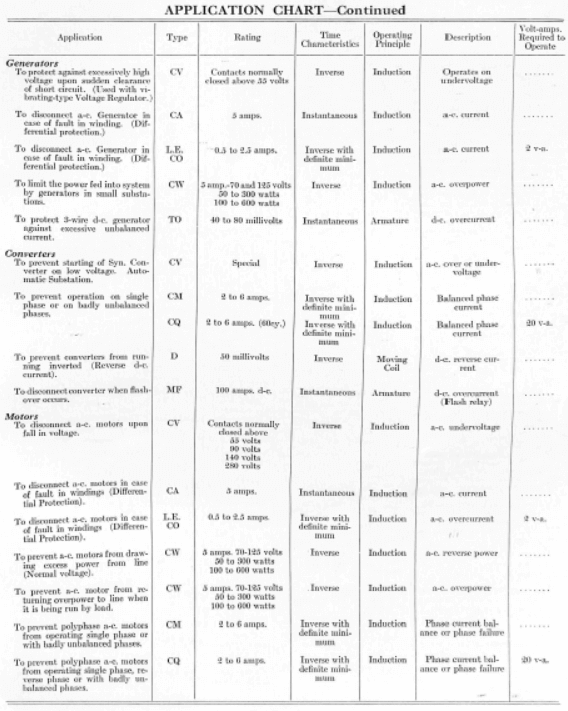
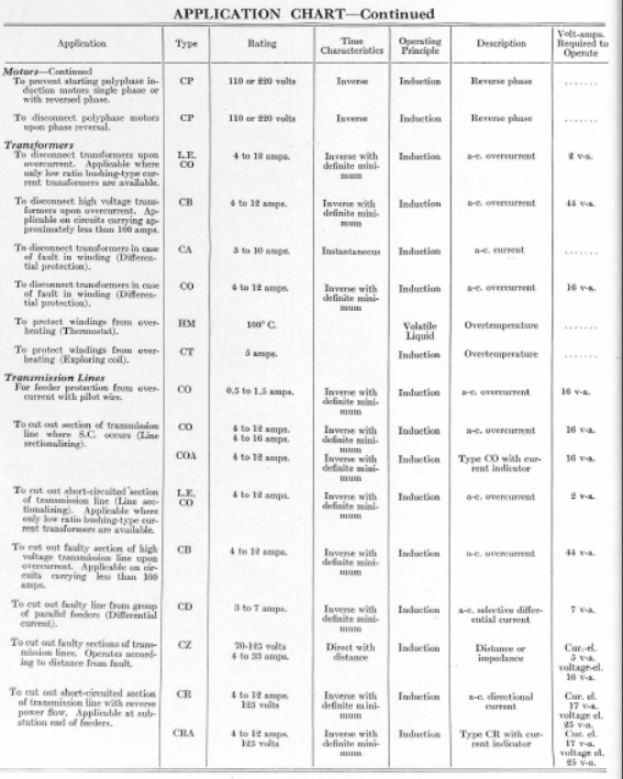
Type CO relays should be used on each outgoing feeder from the several substations. Type CA relays should be used for the differential protection of the three banks of transformers in the generating station. The transformers in the substations also may be supplied with differential protection if their size and location justify it. In most cases, however, where the transformers are relatively small (less than 2000 kv-a.) and where the overload relays may be given a low time-setting, the overload relays serve also as sufficient transformer fault protection.
On complicated systems employing CO and CR relays for protection, the time required to trip sometimes becomes excessive in some parts of the system. This objectionable feature is entirely absent in a CZ installation as all lines have their relays set to clear the line in a maximum time of 0.75 second, with a short at the far end. If the short takes place at or near the relay, the short is cleared almost instantaneously, since the voltage restraining action is zero. The other relays on the system are restrained in proportion to their distance from the short, and accordingly do not open their breakers.
Type CA relays should be used for the differential protection of the three generators.
It should be understood that definite current and time-settings, and final checks on the relay operation can be made only after a short-circuit study of the system has been made, thus determining the actual currents which will flow in different lines with faults at the different locations. After this information is available the proper current transformer ratios and current taps on the relays may be specified, and with the time-setting assumed, the exact time of operation may be found from the relay time-current curve.
Discover more from Valence Electrical Training Services
Subscribe to get the latest posts sent to your email.
Did you like this post?
You can share it with these links:
Read More Articles:
Westinghouse Protective and Control Relays from 1924 Silent Sentinels