Testing Loss-of-Field / Loss-of-Excitation Elements (40)
“Why did my 40-Element test fail?” is probably the most common question I get asked about generator protection.
The first question I ask is, “What kind of fault are you trying to simulate?”
The second question is, “Where are the test currents in relation to their voltages?”
If you truly understand the theory behind Loss-of-Field / Loss-of-Excitation Elements (40-Elements), the answers to these questions will help you perform a successful 40-Element test.
The following sections are excerpts from The Relay Testing Handbook:
Generator Protection Relay Testing, which should help you understand this element and perform successful tests:
Chapter 15: Testing Loss-of-Field / Loss-of-Excitation Elements (40) Excerpt
Generators normally export the VARs necessary for transformers, motors, and other inductive machines to operate. The excitation system controls how much voltage the generator will produce internally, which is the same as the Generator Terminal Voltage when the generator is energized and offline. The Internal Generator Voltage and the Generator Terminal Voltage are different when the generator is connected to a load. The generator will export VARs when the Internal Generator Voltage is greater than the Generator Terminal Voltage. Alternatively, the generator will import VARs when the Internal Generator Voltage is less than the Generator Terminal Voltage.
The same principles apply when the generator is connected to a power grid, except the Power System Voltage will dictate the Generator Terminal Voltage. Therefore, the relationship between VARs and the excitation system is very similar to the relationship between watts and the prime mover. The power system sets the generator’s speed, and the generator’s governor controls watt flow, while the AVR controls VAR flow when the Generator Terminal Voltage is set by the power system. If the excitation system is producing an Internal Generator Voltage that exactly matches the Power System Voltage, no VARs will be imported or exported. If more energy is applied to the excitation system to raise the Internal Generator Voltage, the generator will export VARs. If the excitation system cannot match the power system voltage, the generator will import VARs. You can review these principles in Chapter 2: Section D and Section F.
A loss-of-field (40) condition occurs when something happens to the excitation system that prevents it from applying enough energy to meet or exceed the power system voltage. A generator field could disappear if:
- The Generator Field Circuit Breaker unintentionally opens.
- There is an open circuit or short circuit on the exciter field circuit.
- There is poor brush contact between the rotor and excitation supply.
A generator can import 0.4 to 1.9 times its MVA rating during a loss-of-field condition. This can be catastrophic to the power system because it has to replace the VARs the generator was exporting before the loss-of-field condition, and then possibly supply more to keep the generator online.
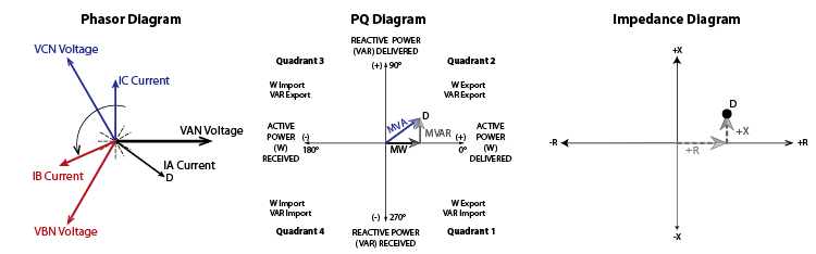
Understanding what happens inside and outside the generator during a loss-of-field scenario will help you create a test plan for 40-Elements. Most generators export watts and VARs under normal conditions, as shown in Figure 15-1:
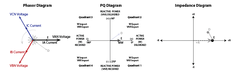
The rotor’s magnetic field strength varies with its excitation current. If the Generator Field Circuit Breaker opens, the rotor’s magnetic field strength drops to residual values and can no longer maintain the Internal Generator Voltage. If the power system can supply enough VARs, the Generator Terminal Voltage will not change because it is fixed by the power system. Nothing happens to the prime mover during a loss-of-field condition, so the generator continues to export the same amount of watts. The generator’s VARs will move from positive to zero over a few seconds, as shown in Figure 15-2.
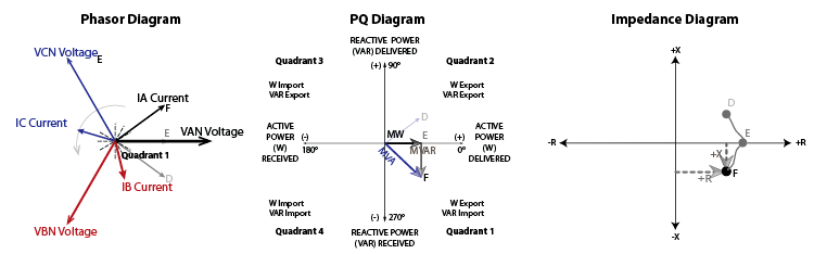
The excitation system can no longer match the Generator Terminal Voltage magnitude, so the power system starts supplying VARs to the generator to keep the Generator Terminal Voltage at Power System Voltage levels. The generator becomes a synchronous condenser that imports VARs and exports watts (remember the prime mover energy and Generator Frequency hasn’t changed, so the power doesn’t change).
The excitation field usually creates the rotor’s magnetic field, but now the rotor’s magnetic field is induced from the stator. The generator is not designed to operate this way, so the rotor and stator will start to overheat, and the end cores of the stator may be damaged.
Notice that the current, VA, and impedance in Figure 15-3 are in the opposite quadrants from where they started in Figure 15-1.
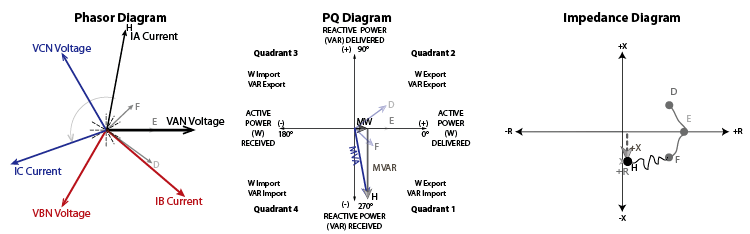
The magnetic interaction between the rotor and stator is weaker than normal, which could mean that the generator and prime mover are no longer 100% magnetically locked together. The prime mover and generator may start to slip, which means that they may start turning at different speeds because the rotor is no longer fully locked to the stator. The generator will export less watts when the rotor starts to slip because watt output is a function of torque on the shaft, which decreases when the magnetic field is weak enough to allow slop between the rotor and stator speeds. The prime mover and generator will be guided by different inertias, which can cause mechanical damage while the prime mover pulsates as it searches for the correct amount of slip to match the system conditions. The wobbly line between points F and H shows the generator slipping in Figure 15-4.
Many design engineers believed that a generator could run under loss-of-field conditions for 2 to 3 minutes without problems, as long as the power system could generate enough VARs to maintain the Generator Voltage. In fact, a famous generator in New Jersey ran without a field for 17 minutes without any negative consequences. However, modern generators are built with much tighter specifications and different materials, which means that damage can occur in less than 10 seconds.
Early Loss-of-Field relays were installed in the excitation circuit, but they were complicated and not very effective. An Over-Leading-VAR relay that operates similar to a Reverse-Power relay seems like a good idea, but VAR-based Loss-of-Field elements tend to operate during normal power swings.
An impedance-based Loss-of-Field relay has proven to be the most reliable and selective method to detect loss of excitation (a different way to say loss-of-field) conditions because the measured generator impedance will drop during loss-of-field conditions, as shown in Figure 15-4. The final generator impedance after the field is lost depends on system conditions and generator loading before the fault. If the generator was lightly loaded before the fault, the final impedance will be near the generator’s synchronous impedance (Xd). If the generator was heavily loaded before the fault, the final impedance will be closer to the generator’s transient impedance (X’d). We covered these topics in Chapter 1: Section G if you are looking for a refresher on Per Unit impedances.
Almost all impedance elements are MHO circles similar to the 21-Element described in Chapter 9 that looks for lagging faults out on the power system. However, Loss-of-Field elements are installed to detect impedance in the opposite direction because the measured impedance during loss-of-field conditions looks toward the generator. Generators are mainly inductive machines, so the expected maximum torque angle will universally lag by 270 degrees in all relays. You should always remember to apply your 40-Element test currents in the opposite direction compared to most relay tests.
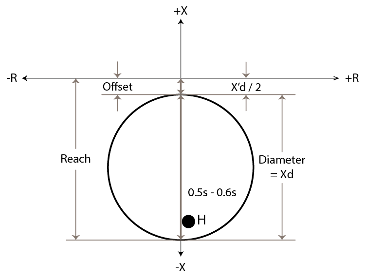
Most 40-Elements are MHO circles, but they do not touch the origin like traditional distance elements because the minimum expected impedance during a loss-of-field condition will be close to the transient impedance (X’d). The distance between the impedance diagram’s origin and the start of the impedance circle is the offset, which is usually set at one-half of the generator’s X’d impedance to ensure the relay will operate even if the calculations are slightly off.
The maximum expected impedance will be near the steady-state impedance (Xd). Therefore, the diameter of the impedance circle should be the generator’s Xd impedance, which will make the final reach slightly higher than the Xd impedance to account for measurement errors. You can use this information to draw the expected impedance characteristic, as shown in Figure 15-5, where point H is the final impedance when a generator was lightly loaded before the field was lost. A normal power swing could enter the characteristic because it is quite large, so a 0.5000 to 0.6000 second time delay is added to allow the power swing to normalize before the 40-Element can operate.
A second 40-Element is usually added with a faster time delay to protect the generator during extreme loss-of-field conditions. This element will use the same offset setting because the generator’s X’d impedance is still the minimum expected impedance. A severe loss-of-field condition will have a small impedance, which means the second 40-Element diameter can be set to the generator’s Per Unit impedance (XPU), as shown in Figure 15-6 where point J is the final impedance if a generator was heavily loaded before the field was lost. This smaller element should have a very short time delay (0.1000s).
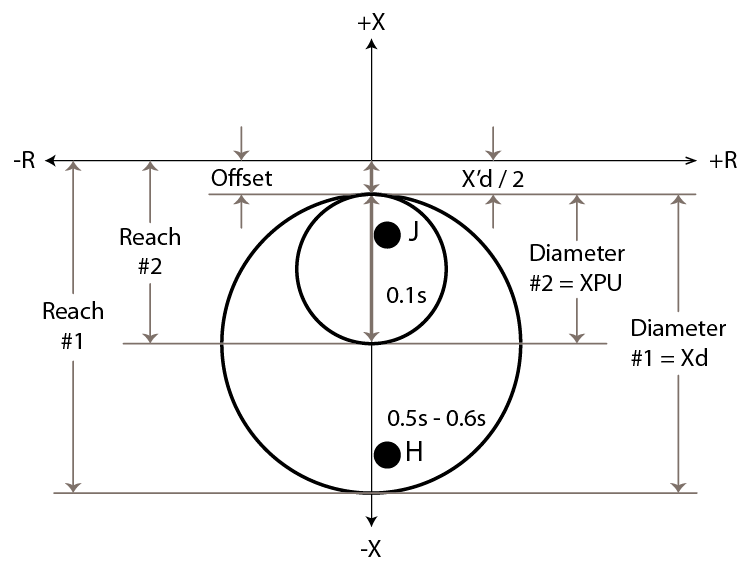
You should look closely at the previous two figures because 40-Elements can use different terminology between relay models and settings. We typically refer to the reach when testing distance elements, but the reach in 40-Elements is the diameter of the circle plus the offset. Some relays define the 40-Elements with Reach and Offset settings, which means you need to calculate the diameter for each element. Other relays define the 40-Elements with Diameter and Offset settings, which means you have to calculate the reach. It is very easy to get confused if you aren’t carefully paying attention to the terminology used.
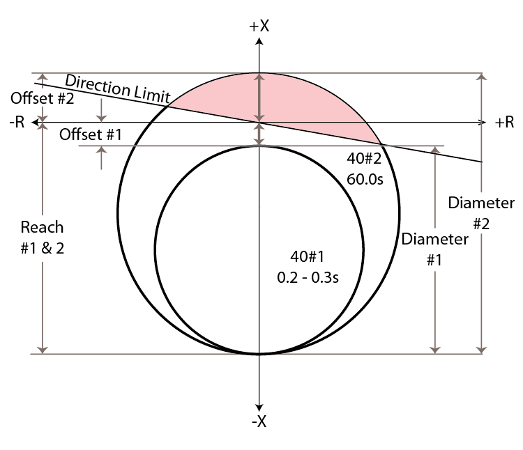
Most relays apply dual characteristic 40-Elements in the negative reactive direction, as shown in Figure 15-6, but the design engineer may have problems coordinating with the generator stability limits described in Chapter 3: Section E: Generator Capability Curves. Ideally, the 40-Element should thread the needle between the Steady-State Stability Curve and the Generator Capability Curve after they have been converted from power to impedance. Figure 15-7 shows the typical interaction between a dual 40-Element application with negative X offset and the Generator Capability Curves.
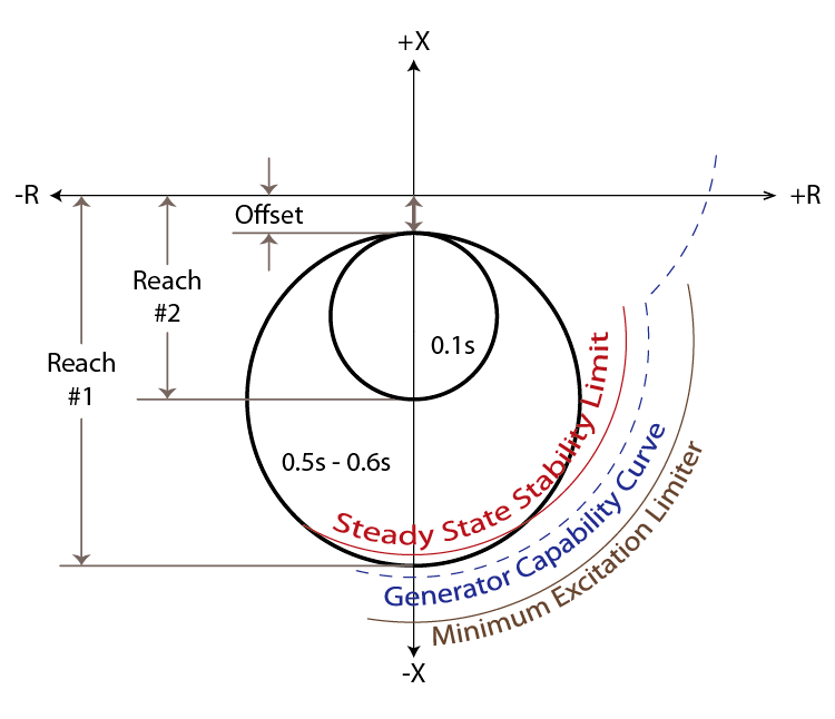
The 40-Element in Figure 15-7 does not thread the needle between the Steady-State Stability Limit and the Generator Capability Curve; therefore the ideal coordination has not been achieved. If this coordination is important to the design engineer, they could create a different characteristic that applies a larger circle offset in the opposite direction, as shown in Figure 15-8:
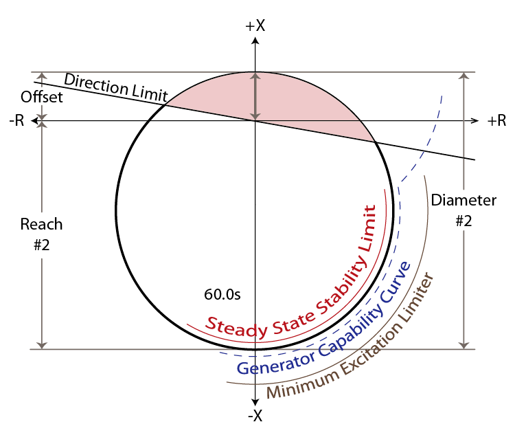
The new characteristic threads the needle between the Steady-State Stability Limit and the Generator Capability Curve, which means optimum coordination has been achieved. The diameter of this new element should be the system impedance (Xs from a power system study) plus the steady-state impedance (Xd); however, the IEEE standard recommends Xs + (Xd x 1.1). The center of the circle should be –j(Xd – Xs) / 2; however the IEEE recommends a positive offset equal to the system impedance with a negative reach equal to Xd x 1.1. The time delay for this new element is relatively high (60.0000s) to ensure that it does not operate during normal stable system swings.
There are a couple of problems that can occur with this new characteristic. A close-in system fault near the generator terminals could fall within the positive X region of the characteristic, which would start a race between the 40-Elements and 21-Elements. A directional element should be applied to block the 40-Element during forward faults, as shown by the red shaded area in Figure 15-8.
The voltage could drop if the power system is unable to maintain the Nominal Generator Voltage, which could cause generator damage during the 60-second time delay before this 40-Element operates. A 27-Element is usually applied with a 0.25-second time delay to ensure the generator is not damaged during severe loss-of-field events. The 27-Element time delay could increase to 1.0000 second if a second 40-Element is applied, as described below.
The second 40-Element will have a smaller diameter and a faster time delay (0.2000s to 0.3000s) to prevent generator damage during severe loss-of-field events. The second MHO element should have the same characteristic displayed in Figure 15-5 with a 0.2000s to 0.3000s time delay. However, the IEEE recommends that the second circle starts at the same offset calculated previously with a diameter that matches the first element’s reach. This dual-element characteristic is shown in Figure 15-9 and should have a 0.2000s to 0.3000s time delay.
Some loss-of-field events could be fixed by simply closing the Generator Field Circuit Breaker, which means that a 40-Element should only operate the Generator Circuit Breaker so the generator can be immediately returned to service after the problem is corrected. A second signal should be sent to an annunciator or SCADA system to warn the operators.
Testing 40-Elements seems hard, but you’ll see that it is relatively straightforward if you follow this test procedure:
[Skipping forward through 8 pages of content describing each setting in detail]
B. Draw the 40-Element Characteristic
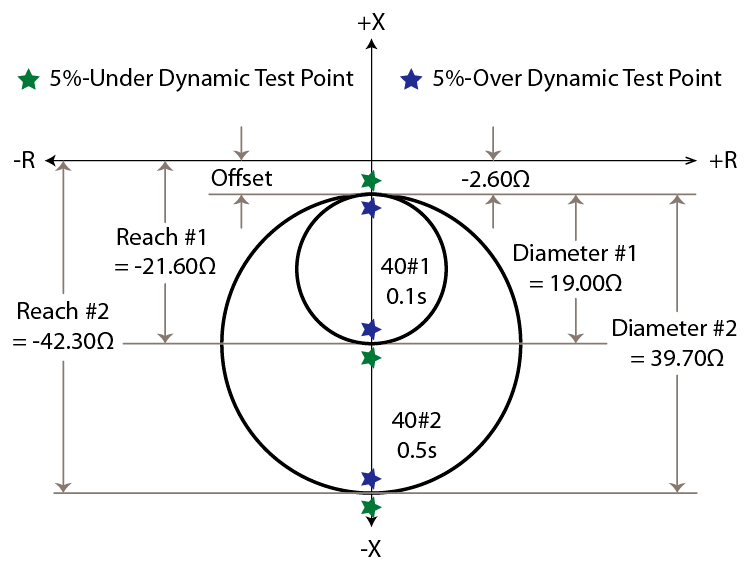
You should start any element test by drawing a picture of the element characteristic to make sure you understand what you will be testing and help find obvious problems with your test. Start drawing the 40-Characteristic by looking at the 40-Element drawings (Figures 15-10 to 15-13) in the relay manufacturer’s instruction manual. The Offset settings for both example relays are negative (-2.60Ω) and the manufacturer’s drawings indicate that a negative Offset setting means that both circles will be below the origin (Figures 15-10 and 15-12 offset is shown as –X’d / 2). Therefore, both circles will start at -2.60Ω, which is below the origin. The diameter is also negative because a loss-of-field impedance will be below the origin.
Each 40-Element will be as large as the Diameter setting at the MTA, which is 270° lag. The example relay characteristics are shown in Figure 15-16 along with the test points we will be applying in this test plan:
C. Get Ready to Perform 40-Element Tests
The first question to ask yourself before starting any element test is, “Which kind of fault do I need to simulate?” A loss-of-field condition affects the excitation system, and there is only one excitation system for all three phases. Therefore, all 40-Element tests are Three-Phase tests. “How do I test a Loss of Excitation element?” is the number one question I get asked, and most of the relay testers with problems apply P-N test values and wonder why the element isn’t picking up. Loss-of-Field tests should always be Three-Phase tests because it is a Three-Phase problem.
The next question to ask yourself is, “Which signals do I need to vary?” Loss-of-Field Elements measure current through the Neutral CTs and voltage through the Generator PTs, so we should fix one set and vary the other to make the math easier. If we pretend that the power system can supply the VARs necessary to keep the Generator Voltage at nominal, then we can fix the voltage outputs to the Generator Nominal Voltage and vary the currents to apply the required impedances.
The next question to ask yourself is, “What other element might operate while I perform my tests?” None of the voltage or frequency elements should operate because we will apply the Generator Nominal Voltage and Frequency for most of our tests. The 27TN-Element should not operate if we apply enough third-harmonic voltage to the relay neutral inputs. The 21-Element will not operate if we apply the correct current angles in the opposite direction. The Inadvertent-Energization (50/27) protection shouldn’t be a problem as long as we apply Prefault states longer than the 50/27-Time Delays.
The Inverse Overcurrent (51V) element may operate, but not if we keep our test durations close to the expected values. The Reverse-Power (32) element may operate if we apply our tests for longer than 10.0000s. However, the maximum 40-Element time is 0.5000 seconds, so it shouldn’t be a problem either. A real loss-of-field event might also trigger the Out-of-Step (78) protection, but not if we keep our tests at the MTA (270° lag).
It looks like we will have clear sailing when performing these tests as long as we keep the state durations as short as possible.
D. Perform a 40#2-Element Timing/Dynamic Test on the Larger Circle
I like to start my dynamic tests with the timing test part first. This proves that your setup is correct, which speeds up your testing time because you won’t waste time rerunning No-Op tests after troubleshooting the timing test when there is a problem with your setup. Use the following procedure to create a 40-Element test:
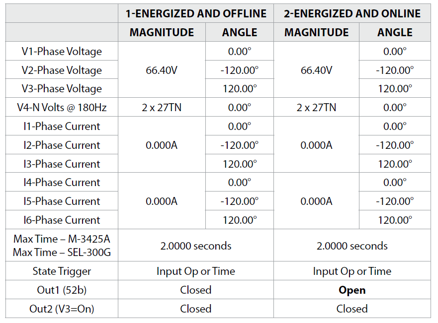
a) Apply an Energized and Offline Test-State
The Energized and Offline State was described in Chapter 5: Section E of this book and should be applied to bypass the Inadvertent-Energization element.
b) Apply an Energized and Online Test-State
The Energized and Online State was described in Chapter 5: Section F of this book and is applied to simulate the correct conditions for a 40-Element test.
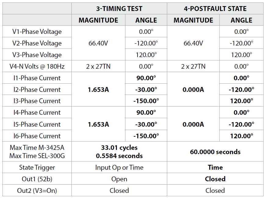
c) Apply a Timing Test-State
Apply a timing test just outside the expected tolerance (40.19Ω to 44.42Ω) for the 40-Element pickup setting (42.30Ω). The smaller impedance tolerance is inside the circle, so your test impedance should be slightly smaller than 40.19Ω, or 40.18Ω. Then use the Ohm’s Law Three-Phase impedance formula to calculate how much current to apply at the Nominal Generator Voltage (A = V / Ω = 66.40V / 40.18Ω = 1.653A). The currents should lag their respective voltages by 270° to simulate a worst-case loss-of-field condition.
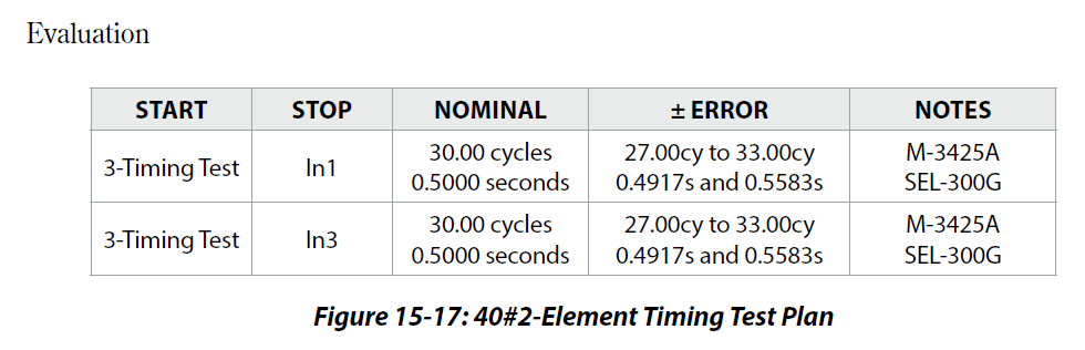
The Beckwith M-3425A time delay tolerance was calculated to be 29.00 cycles to 31.00 cycles based on a 30.00 cycle time delay setting. These specifications probably do not include the relay contact operating time, so we will use the relay tester’s default ±3 cycles time delay instead of digging through all the specifications. Therefore, the new expected delay is 27.00 to 33.00 cycles, and the Max Delay test-set setting should be longer than the maximum time delay tolerance (33 cycles), or 33.01 cycles. Two timers should be added to start when the 3-Timing Test state starts. One timer should stop when Input 1 operates and the second timer should stop when Input 3 operates. Both timers should pass if the measured time delay is between 27.00 and 33.00 cycles.
The SEL-300G time delay tolerance was calculated to be between 0.4917 seconds and 0.5583 seconds with a 0.5000 second time delay. The Max Delay test-set setting should be longer than the longer time delay tolerance (0.5583s), or 0.5584 seconds. Two timers should be added to start when the 3-Timing Test starts. One should stop when In1 operates, and the other timer should stop when In3 operates. Both timers should pass if the measured time delay is between 0.4917 seconds and 0.5583 seconds.
d) Apply a Postfault State
Add a Postfault State to simulate a normal breaker trip situation that opens the circuit breaker and applies nominal volts with zero amps and normal third-harmonic voltage. This state should be applied long enough for you to review the relay targets to ensure the correct information is displayed to the operators, which will be 60.0000s in our test case.
Discover more from Valence Electrical Training Services
Subscribe to get the latest posts sent to your email.
Did you like this post?
You can share it with these links:
Read More Articles:
New Online Seminar for Overcurrent Testing is Now in Production
Good information for relay testers! I am retired now but have tested relays all my working life.
Allentown, PA.
Thank you for the kind words.
When is the complete book on Generator protection testing being released?
A pre-release sale will be sent out to subscribers of our mailing list in a couple of weeks. We hope to have books in the warehouse for regular sale mid-August.
Why does power line spacing on transmission towers important?
Because there’s no insulation on the wires and they can arc together or to ground if they are too close. It will also affect the X / R ratio of the power system, which can cause brownouts if the ratio is out of balance.
Dear Sirs
Kindly help me to understand the below points:-
(( Generators are mainly inductive machines, so the expected maximum torque angle will universally lag by 270 degrees in all relays. )).
((You should always remember to apply your 40-Element test currents in the opposite direction compared to most relay tests.))
KR
We wrote a whole book about generator protection testing you can buy here: https://relaytraining.mystagingwebsite.com/relay-testing-handbook-series-v3/
Dear sir
Kindly guide me to conduct loss of Excitation test with help of single phase injection test kit that I had for SR489 GE Multilin relay for generator.
Settings: circle1 = dia 27.0 ohm, offset = 2.1 ohm, time delay = 2sec, circle2 = dia 38.5 ohm, offset = 2.1 ohm, time = 5.0 sec
Need procedure for testing.
Thanks & regards
Ramkumar.R
I doubt you will be able to perform many single-phase test on a 489 because it probably measures all three currents and voltages. The only modern relay I know of that only uses one phase current is an Alstom, and you probably still need three voltages for it.
The procedure for testing a 40-Element properly with three-phase is in this post and The Relay Testing Handbook: Generator Relay Protection Testing