How to Measure Phase Angles with a Phase Angle Meter
I’ve noticed that many students don’t seem to have experience with phase angle meters, and they can’t guess what a phase angle meter would measure in simple circuit. This knowledge is CRITICAL if you want to perform a protective relay meter test properly. Anyone can inject voltages and currents into a relay and record the results on a test sheet. A good relay tester can interpret those results and find MAJOR relay setting and installation problems with a simple test.
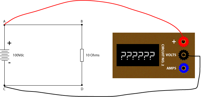
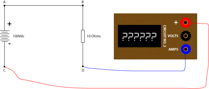
Let’s take a look at a simple DC circuit to start:
What would you measure if you connected the meter’s red (+) terminal to A, and the meter’s Volts (Volts) terminal to C as shown in the next drawing?
Did you choose +100V?
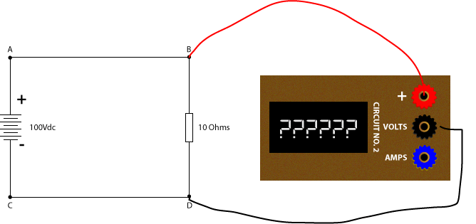
What if you connect (+) to B and (Volts) to D as shown in the next drawing?
It would be +100V because you’re still connected to A and C minus a small voltage drop, which we can ignore for our example.
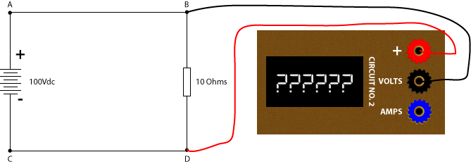
What would you measure if you connected (+) to D and (Volts) to B as shown in the next drawing?
The meter measures the voltage drop across the two terminals, which would be negative because the positive meter lead is connected to the negative battery lead. The meter reading would be -100V.
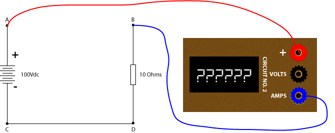
What if you removed the wire between A and B and connected (+) to A and (Amps) to B?
The measured current would be +10A, using Ohm’s Law (100V/10Ohms).
What if you replaced CD with (+) and (Amps)?
The current magnitude is the same, but the current direction would be opposite. The meter would measure -10A.
You should be able to see in our DC circuit that:
- the voltage sets the potential energy as well as the direction of current flow,
- the load (resistor) determines how much current will flow for a given voltage, and
- the measured polarity is dependent on the lead connections, not the circuit.
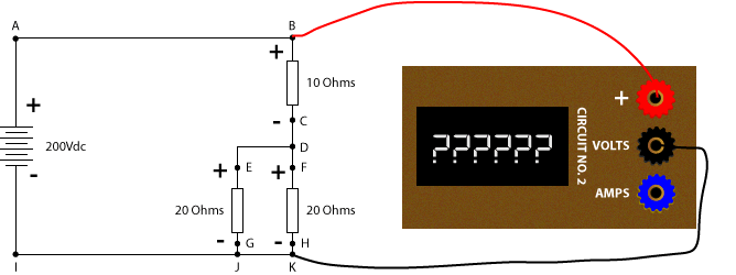
Let’s try a more complicated circuit:
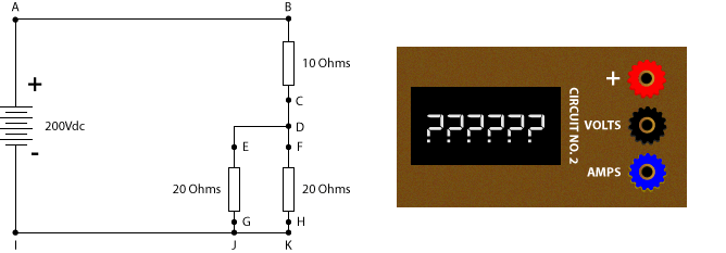
What would you measure across B (+) and K (Volts)?
You would measure +200V.
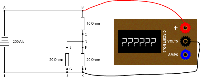
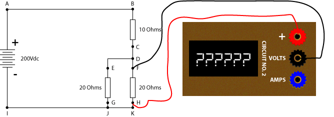
What about H (+) to F (Volts)?
You would measure -100V because:
- D-K has two 20 Ohm resistors in parallel, which provides an equivalent resistance of 10 Ohms.
- B-C is 10 Ohms and is in series with D-K, creating an equal voltage divider. There will be ½ voltage across D-K.
- D and F are the same point and K and H are also the same point; so there will be 100V across H-F.
The meter leads are opposite to the battery; so the measured value will be -100V.
Can you fill in this chart?
| (+) Connection | (Volts) Connection | Measurement |
| A | I | |
| A | K | |
| A | D | |
| D | K | |
| G | D | |
| C | B | |
| K | A |
Want a hint?
It helps if you put polarity marks across each resistor.
Now if the (+) lead is on the same side of a positive of the circuit and the (Volts) lead is connected to negative, the result will be positive.
Here are the answers
| (+) Connection | (Volts) Connection | Measurement |
| A | I | +200V |
| A | K | +200V |
| A | D | +100V |
| D | K | +100V |
| G | D | -100V |
| C | B | -100V |
| K | A | -200V |
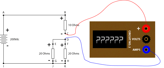
Now let’s look at DC current
What would you measure if the meter replaced the wire between C (+) and D (Amps)?
The meter would measure +10A because the (+) and (Amps) terminals are in the same polarity of the resistors above and below the measuring points.
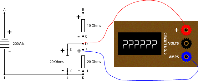
What would you measure if the meter replaced the wire between D (+) and F (Amps)?
You would measure +5A because there is +10 Amps flowing into D, which will split in half because both paths have the same resistance. Therefore, +5A flows into E, and +5A flows into F.
Can you fill in this chart?
| (+) Connection | (Amps) Connection | Measurement |
| A | B | |
| C | D | |
| D | E | |
| F | D | |
| K | H | |
| G | J | |
| I | J |
Here are the answers
| (+) Connection | (Volts) Connection | Measurement |
| A | B | +10A |
| C | D | +10A |
| D | E | +5A |
| F | D | -5A |
| K | H | -5A |
| G | J | +5A |
| I | J | -10A |
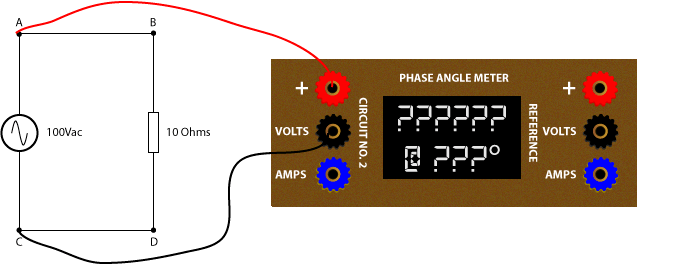
Now let’s look at a simple AC Circuit with a phase angle meter.
Phase angle meters measure magnitudes AND angles based on a reference angle.
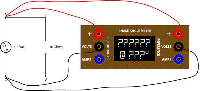
Can you guess what the phase angle meter would measure in the following figure?
The phase angle meter would measure 100V, but the angle will be a random number that might change constantly because the phase angle meter does not have a reference.
You can walk up to any part of a DC circuit and measure the voltage drop across (or current flow through) a device because there is only one direction in a DC system, using the metering definitions of positive to negative. (I know that physics defines it as negative to positive, but that’s not how our meters work.)
You can measure the magnitude of current and voltage in an AC system much like a DC circuit, but the AC waveform is switches constantly from positive to negative with every cycle. This makes the “polarity” of the circuit much harder to define.
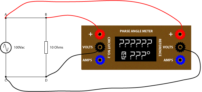
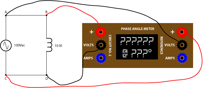
Our AC circuit has a starting point, but our phase angle meter has no way of recording that without a reference. We can measure the phase angle by adding a reference connection as shown below.
Now what would the phase angle meter measure?
The phase angle meter would measure 100V @ 0° assuming that the reference is calibrated to zero degrees.
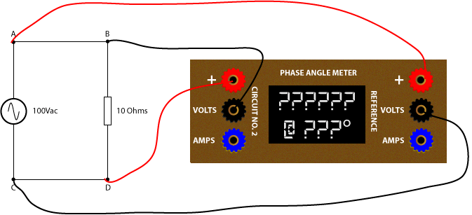
What would the phase angle meter measure using the following figure?
It would still measure 100V @ 0° because the measuring inputs and reference inputs are connected in the same direction.
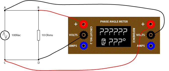
What would the phase angle meter measure now?
It would measure 100V @ 180° because the measuring inputs and reference inputs are connected in the opposite direction.
It is important to note that the CIRCUIT has not changed. The reason the last two angle measurements are different is because of our CONNECTIONS, just like switching the leads on a DC meter.
One last easy one. What would the phase angle meter read now?
It would measure 100V @ 180° because the measuring inputs and reference inputs are connected in the opposite direction.
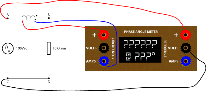
Now we can put a CT in the circuit to measure the current flowing through the resistor.
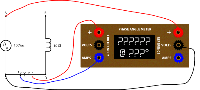
What would the phase angle meter measure in the next circuit?
The phase angle meter will measure 10A @ 0° because the polarity of the reference is the same as the measuring circuit.
We can redraw the circuit with polarity marks to better see how the current going into the CT primary polarity mark comes out the secondary polarity mark to match the polarity of the reference.


What would the phase angle meter measure in the next circuit?
The phase angle meter will still measure 10A @ 0° because the polarity of the reference is the same as the measuring circuit.
The dirty little secret of CTs is that polarity marks don’t matter once the CT installation matches the drawings. Direction of current flow is all about the reference in phase angle meters. In this case, our phase angle meter leads haven’t changed.
If we use the polarity marking from the previous drawing, we assume the current flows from A to B because our reference leads are connected with polarity on A and non-polarity on C. The current flows into the primary non-polarity mark of the CT; so current will flow out the non-polarity mark of the CT into the plus terminal, making the phase angle measurement 0°.
What would the phase angle meter measure in the next circuit?
The phase angle measurement would measure 10A @ 180° because the reference tells us that a 0 degree current would flow from A to C and our + measurement lead is connected to C, opposite the reference.
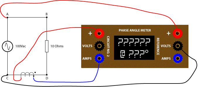
100% resistive circuits will always be at 0° or 180°.
Can you fill in this chart with voltage measurements with a phase angle meter?

| (+) Connection | (Volts) Connection | Measurement |
| A | I | |
| A | K | |
| A | D | |
| D | K | |
| G | D | |
| C | B | |
| K | A |
Here are the answers
| (+) Connection | (Volts) Connection | Measurement |
| A | I | 100V @ 0° |
| A | K | 100V @ 0° |
| A | D | 50V @ 0° |
| D | K | 50V @ 0° |
| G | D | 50V @ 180° |
| C | B | 50V @ 180° |
| K | A | 100V @ 180° |
Can you fill in this chart with current measurements with a phase angle meter?
Imagine the CT polarity is connected to the [+] terminal as shown in the AB example below and the [+] and [Amps] designations in the chart determine the direction of the CT.
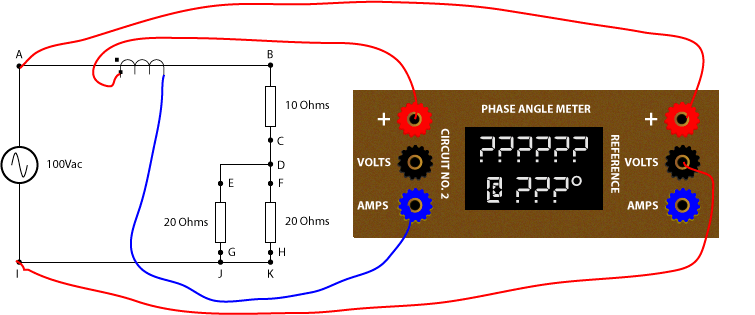
| (+) Connection | (Amps) Connection | Measurement |
| A | B | |
| C | D | |
| D | E | |
| F | D | |
| K | H | |
| G | J | |
| I | J |
Here are the answers
| (+) Connection | (Volts) Connection | Measurement |
| A | B | 5A @ 0° |
| C | D | 5A @ 0° |
| D | E | 2.5A @ 0° |
| F | D | 2.5A @ 180° |
| K | H | 2.5A @ 180° |
| G | J | 2.5A @ 0° |
| I | J | 5A @ 180° |
What happens if we connect our phase angle meter to non-resistive circuits?
What voltage would you measure with a 100% capacitive circuit as shown in the next figure?
You would still measure 100V @ 0° because the source determines the voltage, not the load.
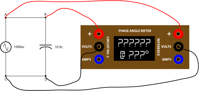
What current would you measure with a 100% capacitive circuit as shown in the next figure?
You would measure 10A @ 90° lead because the capacitive current will lead the voltage by 90°.
Notice I didn’t specify +90° or -90°? That’s because different devices can have different phase angle designations for the same position. The best way to communicate phasor information accurately is to use “lead” and “lag” designations instead of absolute references.
We cover this topic in our Phasor Drawings for Relay Testers Online Course
What would the phase angle meter measure in the next circuit with 100% pure inductance?
The phase angle meter would measure 100V @ 180° because the reference connections are opposite the measurement connections.
What current would you measure with a 100% inductive circuit as shown in the next figure?
You would measure 10A @ 90° lag because the inductive current will lag the voltage by 90° and the reference and measurement leads are in-phase.
You should be able to see by now how important the REFERENCE of your phase angle meter is. Remember, every device that measures phase angles MUST have a reference, and that reference may not be what you think it is. Some phase angle meters use whatever they are plugged into as the reference. Some use whatever is connected to V1, Van, or Vab. Some use whatever is connected to I1 or Ia. If you don’t know the reference, you can’t verify that your measurements are correct.
Also remember that the system determines the voltage magnitude and angle and the load determines the current and current angle. There is no such thing as a purely resistive, capacitive, or inductive loads. This means that you should never apply current at 0°, 90° lag, or 90° lead because your relay or meter will never see these values in the real world. Always try to simulate realistic conditions whenever possible.
You now have the foundation necessary to understand what happens during a meter test. Try to figure out what you are supposed to measure before you perform your next meter test. You can get some help with our Finding the Direction in Directional Overcurrent Relays post before we cover meter testing in a future post.
Discover more from Valence Electrical Training Services
Subscribe to get the latest posts sent to your email.
Did you like this post?
You can share it with these links:
Read More Articles:
Help with 27/47/59N Protection in an SEL-387E
The E-mails are awesome, keep-em coming. I might be mistaken, I think the answers for question 20 might be off. (Can you fill in this chart with voltage measurements with a phase angle meter?)
Thanks. What do you think is off?
I noticed a misprint on some of your “fill in the table” questions. The DC diagrams use a point “I”, but this point changes to point “C” in the AC section. However, point “I” is still in the tables to be filled out instead of “C”. Confusing at first.
Other than that, outstanding content! Keep it up!
Thanks for letting me know. I knew something was wrong in the back of my head, but didn’t see it. Should be all fixed now.
Really interesting and provide so many feedback specially for beginners. Senior engineers get benefit as well recalling some concepts.
Great job!
Very good, it is benificial to test oneself at times. Keep the E-mails coming enjoy all.
What phase angle meter do you suggest? Is Arbiter the king, or are there other good options?
Arbiter is the most complete with lots of options, but that usually means added complexity. The ones from Megger are fine. Manta used to sell some simple ones that are all a relay tester need, but they are pretty dated.
Thank you for this, I have been working through the relay training program, and this help me gain a better understanding.
Such an AMAZING! examples.
Thanks Chris!
The phase angle measurement examples are great. and the activities look simpler However,. In real life they are not so., it means adding phase angle meter current coil in series with CT secondary circuit without open circuiting secondary. The probable risk may be highlighted during training stage.