When I test induction disc relay type … Is the pickup value the value at which the disc starts rotating?
This question was submitted via the Ask Chris form where you can ask me relay testing questions that I can hopefully answer.
Creating test plans for digital relays is often difficult because you can have ten relays with identical model numbers that have completely different functionality. Conversely, ten induction disc relays of the same model will have identical functionality that is rather limited compared to their digital counterparts. With limited functionality and identical operating characteristics for around 100 years, you would think that we have all agreed on the “right” way to test an induction disc relay.
I thought this was an easy answer until I started doing a little research. Here is the official acceptance pickup test procedure from the ABB/Westinghouse CO instruction bulletin CO 41-100K:
“6.2 – MINIMUM TRIP CURRENT – Set the time dial to position 6 using the lowest tap setting, alternately apply tap value current plus 3% and tap value current minus 3%. The moving contacts should leave the backstop at tap value current plus 3% and should return to the backstop at tap value current minus 3%.“
Here is the official acceptance pickup test procedure from the GE IAC instruction bulletin GEI-98317A:
“Set the relay at the 0.5 time dial position and minimum tap. Using the test connections of Figure 8 the main unit should close its contacts within +/-5% of tap value current.“
I’ve never seen anyone perform either of these contradictory tests as described above, and you shouldn’t perform them either; unless you are performing an acceptance test. In fact, I performed a similar test very early in my career that cost me, and whoever came after me, a lot of grief. I was sent out to a mine in the middle of nowhere to test over 70 CO electro-mechanical relays. I was pretty green with no formal training, so I made up my own pickup test procedure based on the principle that you should never change the relay settings unless it is a last resort and you should always try to simulate real-world conditions.
- Step 1: Record all the settings on my test sheet
- Step 2: Make sure the relay is completely reset to simulate real-life conditions
- Step 3: Slowly ramp the current until the disc starts to move
- Step 4: Record the pickup result on the test sheet
I thought I was doing the right thing, but almost all the relays were out of tolerance and had to be adjusted. I had heard of relay drift, but this just seemed unreasonable. Did the guy before me even test the relays, or did he just pencil-whip the results? I looked at the old test sheets and made sure to give him a piece of my mind when I got back to the office.
It turns out that he was a MUCH more experienced relay tester than I was, and he explained the procedure that most people use to test pickup on induction disc relays.
- Step 1: Get the disc to the tripped position by applying more current than the pickup setting
- Step 2: Set the current slightly higher than the pickup setting (105%)
- Step 3: Slowly ramp the current down until the relay contacts just open. (This is called the dropout)
- Step 4: Immediately change directions at the same pace and raise the current until the contacts just close. (This is the pickup)
These procedures are quite different than the ones in the instruction manuals and my “real-life” simulation, so why does everyone do it differently? And why were the results so different?
Let’s start with a quick look at the electro-mechanical relay operation:
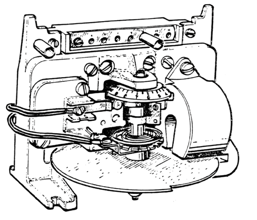
The major pickup setting is defined by the tap, which is an auto-transformer that energizes a shading coil surrounding the disk. A lower tap means that you need less current to push the disk around to the trip position. A small spring pushes the disc in the opposite direction towards the backstop, or reset position. You can make minor adjustments to the pickup by changing the spring tension, which is really the only force working against the applied current. This means that spring tension is the defining factor when testing pickup.
The two pickup procedures from the instruction manuals specify exact taps and time dials for their acceptance tests because these are the exact conditions that the relays are calibrated to operate to. Changing the time dial will change the spring tension, which will change the pickup characteristics. You should always test a relay with in-service settings, so we can’t use these acceptance test procedures for maintenance tests.
My “real-life” method also has some problems. What happens when the relay time dial setting changes in between maintenance periods due to changing loads or fault capacity? Is pickup when the disc shakes on the backstop, leaves the backstop, turns at a specific rate of rotation, or doesn’t move to the backstop? Every one of these is a possibility, and every relay tester might perceive pickup differently. How can we automate this procedure with our modern test-sets? Do we need to buy a special disc rotation analyzer?
The test procedure that most relay testers use forces the same spring tension on every test. If all relays are tested at the trip contacts, the spring tension will be the same for every test, and we are more likely to get consistent results from different relay testers across multiple maintenance intervals. We are monitoring contact status with this test, so we can apply automation to remove the human factor from the tests to make them even more accurate.
Finally! The answer to how you should test an induction disc relay’s pickup
Technically you should set the relay to the specific parameters described in the instruction manual, but these test procedures have the following problems:
- They are contradictory, which means different procedures for different models
- They are impractical for maintenance testing because you have to change the settings and are not proving that the relay is functional at the in-service settings
- They do not allow automated control for more reliable results without external equipment
- Two different testers will likely get two different test results
Use the standard test procedure most testers, and automated test software, perform so that:
- Everyone uses the same procedures on all relays
- You’ll be making sure the relay operates under in-service conditions
- You can automate the test results
- There is a better chance that different relay testers will get consistent results across maintenance intervals.
Besides, that’s what all the cool relay testers are doing already ;)
Share the Knowledge
Please share and like this post if you liked it. It helps us get noticed, which means we can keep offering free content like this.
Have a burning question you want answered? Go to the Ask Chris form and I might have an answer for you!
Discover more from Valence Electrical Training Services
Subscribe to get the latest posts sent to your email.
Did you like this post?
You can share it with these links:
Read More Articles:
Methods of Clearing Ground Faults from Silent Sentinels 1924
Good explanation for pick up tests……………..in my opinion the relay should be tested only on service settings because the relay has to operate in service conditions .
We use only in-service conditions. Many years ago (before I started here) they used to test per IL (Instruction Leaflet). Then one day, during normal maintenance they forgot to put the tap back at the in-service setting and either the breaker didn’t trip or false tripped (Sorry, I forgot).
We do test the tap as per the ABB IL (as Chris quoted above), but we don’t do the -3%.
I totally agree with Chris’ statement about the variance between test sets and even relay technicians, but I see the importance of at least checking the functionality of the MPU (minimum pick-up).
Sorry for running on!
Alan
HECO Relay Tech