Automatic Control for Electrical Systems
Silent Sentinels 1924 Excerpt #9
This excerpt from the 1924 version of Silent Sentinels discusses automatic control in the electrical system. This is the 9th in the series. Follow these links to learn more about this series and the 1924 version of Silent Sentinels.
Automatic Control
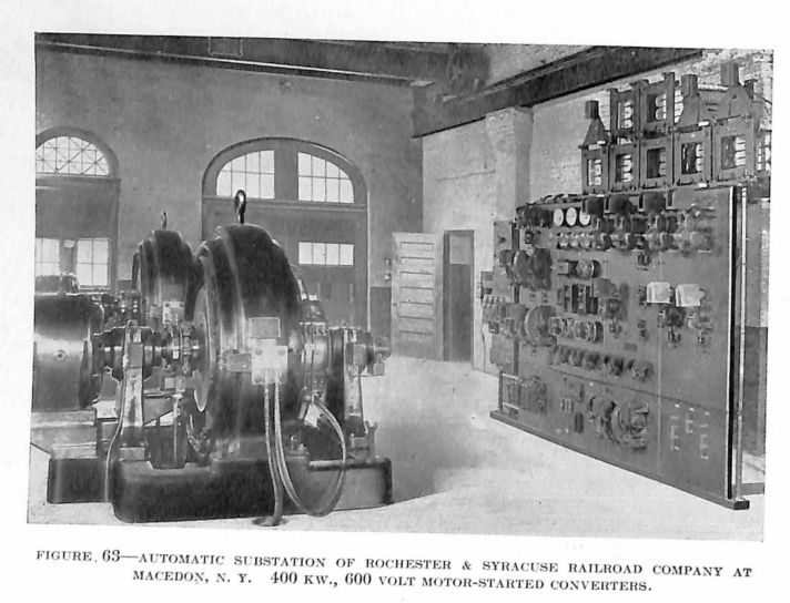
Substations, depending on the method used in their operation, may be divided into three classes,—manual, semi-automatic and automatic. Regardless of its type a station must be a highly reliable source of power supply.
The necessary operations in a substation which serves the purpose of transforming alternating current into direct current by means of synchronous converters or motor-generators are, therefore, the starting and stopping of such machines when the system demands it, and the provision of adequate protection against faulty action either in case of some trouble out on the system, or in case of trouble within the substation equipment. The automatic substation, today, is more dependable than is the manually-operated station. The design and development of relays with a high degree of accuracy, sensitivity and reliability have made such an automatic substation a possibility.
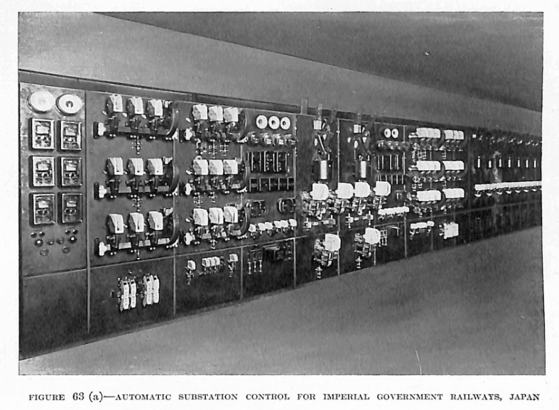
The characteristics of the automatic substation, which must be supplied by adequate relays, might be roughly divided into two classes, namely, control and protection. The control methods consist in the automatic starting of one or more of the machines in the station. This may be introduced in any one of several ways depending on the conditions to be met, and is generally accomplished through some form of remote control, or by means of a voltage relay which closes its contacts at some predetermined value of reduced line voltage. Starting, due to momentary drop in voltage, or when the alternating-current voltage conditions are incorrect, is prevented by an induction-type alternating-current voltage relay.
While many of the operations are common to both synchronous converters and motor-generators, the following outline of system is especially applicable to synchronous converters.
When conditions are favorable for starting, a sequence of relay actions serves to perform the necessary functions, such as lifting the converter brushes, connecting the converter to the starting tap of the power transformers, and other operations depending on the type of substation. After the converter has started to rotate, synchronism and polarity are indicated by a polarized motor relay, which, in case of reversed polarity, causes the polarity of the machine to be corrected by reversing the field. The armature of the relay motor is connected to the converter pilot brushes, and during the period of starting, the polarity of the relay becomes that of the machine. As the converter comes up to synchronous speed, alternating current of diminishing frequency flows through the motor armature until synchronism is reached without causing rotation. At that time, the armature will revolve, and drive a drum switch in the direction corresponding to the converter polarity. If the polarity is incorrect, the drum switch causes the field connection to reverse by means of a double throw contactor switch. The reversed connection is maintained only long enough for the voltage to fall to zero, and then to release the controlling relay which causes the normal field connection to be re-established. By this operation, the converter has been caused to slip a pole, and thus correct the polarity. The polarized motor relay continues to operate, and causes a transfer relay to function. This relay, in turn, opens the starting contactor, causing operation of the direct-current brush-operating mechanism which lowers the brushes to the commutator. At this time, the main direct-current switches are closed, and the machine is connected to the load.
The final function of the control part of the substation equipment is to disconnect the machine from service. This operation is introduced by the action of a sequence of light-load control relays.
Protective equipment is provided not only in the automatic substations, but also in the manually-operated or the semi-automatic stations. It is provided by induction-type single and polyphase relays which prevent the station from starting under abnormal conditions of alternating-current line voltage, such as low-voltage, open-phase, or reverse-phase. This same type of relay causes the station to shut down on unbalanced phase conditions. If the trouble is within the station, a lockout relay prevents restarting, and if the unbalanced phase condition is outside of the station, the automatic equipment functions to bring the apparatus into service as soon as the line is restored to normal. Each bearing is equipped with a thermostat which in case of a hot bearing, locks the machine out of service until the contacts of the thermostat device have been reset by hand.
A thermal relay also protects the winding of the machine from overheating due to continued overload. Other protective devices are the direct-current directional relay, an overspeed device, an inductive-type alternating-current overload relay, a thermostat preventing overheating of the current limiting resistors, and a lockout relay which locks the equipment out of service in case of failure of any part of the apparatus.
The protection of the equipment is complete, and responds immediately in case of trouble, thus eliminating the losses which often occur in manually-operated substations, because of the very impossibility of handling an emergency in the required time or the inability of the operator to do so.
In addition to this automatic operation of the sub-station, a number of automatic selective relay equipments are in use, for automatically cutting out a short-circuited line or for automatically reclosing and other types of necessary feeder operation.

It can be seen from this description what a large part the relays play in automatic substation equipment and also how absolutely necessary it is to have relays which are not only highly reliable, and accurate at the time of their installation, but also which will maintain this high degree of accuracy and reliability throughout continued service. The success of the Westinghouse automatic substations, and past experience, have proved the induction type of relays, first developed and manufactured by the Westinghouse Company, to be especially suitable for this type of service. By the use of the induction-type relays, precision of operation is not only assured, but the exact calibration can be maintained throughout a long period of operation. Tips, the induction relay has solved many of the difficulties which were formerly experienced when plunger-type relays had to be depended on for the various functions.
Most of the relays supplied with the present-day automatic substation equipment are standard protective relays as described elsewhere in this publication. In some cases, it is necessary to somewhat modify the characteristics of the relay, but the fundamental principles of design and operation are maintained. The CV voltage relay is used throughout as a timing voltage relay to provide a definite time delay where necessary. A slight modification of this relay consists in having the contacts geared to the disc shaft rather than mounted directly on it, which provides a relay with a much longer time delay characteristic than the standard. The GK time-delay relay, also used largely in automatic substation equipment, is motor operated, and is highly reliable.
A recent addition to the relay family is the MF flash relay which is used in automatic substation protection to disconnect the rotary in case of a flashover occurring between the commutator and the frame.
Discover more from Valence Electrical Training Services
Subscribe to get the latest posts sent to your email.
Did you like this post?
You can share it with these links:
Read More Articles:
What is DC Offset? Ask Chris