Testing Basler BE1-47N Negative Sequence Voltage Relays
Testing more complicated elements that use a percentage or ratio between values can be difficult if you cannot properly define all of the values in the equation. It doesn’t help that different people can define the same element using different terms, especially when they don;t define their terms in their documentation.
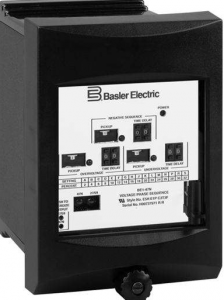
We were attempting to test a Basler BE1-47N negative Sequence Voltage relay. This relay measure the percentage of negative sequence voltage in a system. Negative sequence is universal [V2 = (Va + a2Vb + aVc)/3], but our test set used the formula %V2=100 x V2/V1 and the results were OK when the pickup setting was very small. As the pickup grew, the percent error between expected and actual test results increased. We could not find the formula in the manual and tech support at Basler was unable to help us either.
We figured out that the relay uses the formula %V2=100 x V2/V1nom. The relay’s nominal voltage was 120V P-P which would be 69.28V P-N.
V1 gets smaller when V2 increases, so the difference between the test-set V2% and the relay’s V2% grew as more V2 was applied.
Always know how the relay and your test-set calculate values so that you can compare apples to apples!
Discover more from Valence Electrical Training Services
Subscribe to get the latest posts sent to your email.
Did you like this post?
You can share it with these links:
Read More Articles:
Good Directional Overcurrent Protection (67) Video
Hi Chris. I am testing one of these tomorrow. Do you have a more detailed to your approach. I am a member of your training and have purchased both your testing handbook and your motor testing handbook.
Connect your test-set to the relay as per the site 3-line drawing and monitor the correct outputs.
Apply nominal voltage in the correct phase rotation.
Lower or raise one voltage until the relay pickup light operates.
Negative sequence voltage(V2) = (PickupV – nom volts )/3
Normal %V2 would be 100*V2/V1 where V1 = (PickupV + Nominal Volts + Nominal Volts)/3
This relay uses %V2 = 100*V2/Vnom
Compare to expected pickup and tolerance.
Determine a point on the curve you want to test for timing
Re-arrange the formula to find out how much voltage TestV = Nominal Volts +/-((3*Nominal Volts * Test %V2)/100)
Perform a timing test.
For a 2%V2 pickup, the expected Test Volts should be 69.28 +/- 4.1568V, assuming a 120V p-p nominal voltage. (eg. Pu measured 65.2V, V2 = ((65.2 – 69.28) / 3) = -1.36V, %V2 = 100*V2/Vnom = 100 * -1.36V / 69.28 = 1.96%V2
A timing test at 6% should have 2 phase at the nominal voltage (69.28V) and one TestV = Nominal Volts +/-((3*Nominal Volts * Test %V2)/100) = 69.28 – ((3*69.28 * 6)/100) = 56.81V.
Hope that helps!
thanks for the information