How to Understand and Determine Phase Rotation in a Power System
Understanding phase rotation is vital when connecting two systems together because the results can be catastrophic if someone doesn’t understand how to interpret phase rotation drawings. You would think something as important as phase rotation would have consistent terms across the entire industry. Unfortunately, you’d be wrong.
Let’s start with a refresher on generator theory.
The video below shows a generator with “clockwise rotation” because the generator rotor is rotating clockwise inside the stator. I think this is a terrible definition because the rotor would appear to be rotating counter-clockwise if you walked it around and looked at the opposite side of the generator. It all depends on your perspective. Some people refer to the voltages created by this generator to be “clockwise” because if you start with A:
- the A-Phase Voltage reaches its peak first,
- followed by the B-Phase Voltage, and then
- followed by the C-Phase Voltage.
A counter-clockwise generator can be defined as a rotor that rotates counter-clockwise inside a stator as shown in the following video. Some people would refer to the voltages created by this generator to be “counter-clockwise” because if you start with A:
- the A-Phase Voltage reaches its peak first,
- followed by the C-Phase Voltage, and then
- followed by the B-Phase Voltage.
Both of these definitions are a terrible way to communicate phase rotation.
For example, which phase sequence is the voltage output of the generator in the following video?
The generator is rotating clockwise, but the voltages are counter-clockwise because the A-Phase Voltage reaches its peak first, followed by the C-Phase Voltage, and then followed by the B-Phase Voltage.
Which is the correct term for this system…clockwise or counter clockwise? Both apply, don’t they? That’s why this definition of phase rotation is confusing.
We don’t care which direction the generator turns in the power system. We want to know the order, or sequence, of voltages being produced by the generator and to make sure that the system has the same phase sequence before connecting the two. Therefore, you should banish clockwise and counter-clockwise from your terminology if you want to effectively communicate phase sequence information with someone else.
How to Determine Phase Rotation from Waveform Drawings
The correct terminology to use should reference the voltage designations, and always start with the same designation.
The A-B-C-A-B-C system in the next image is an A-B-C system if I choose A as a reference.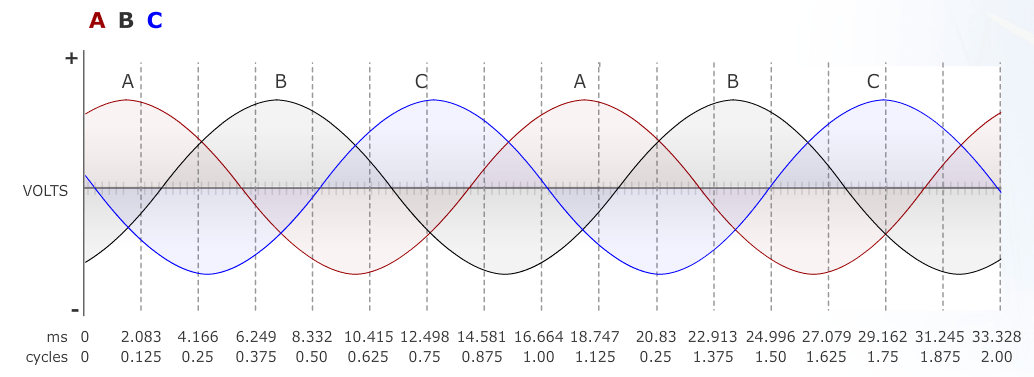
![]()
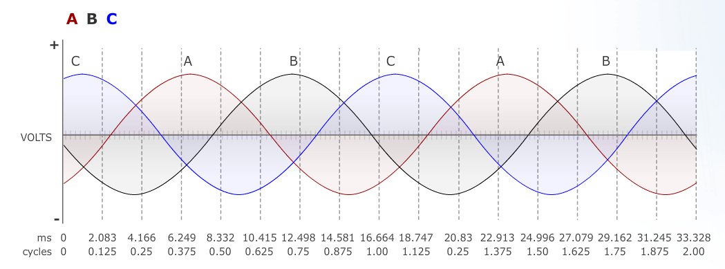
The image below shows a C-A-B-C-A-B system, which is also an A-B-C system if I use A as a reference. It could also be called a C-A-B system, or a B-C-A system, depending on the reference.
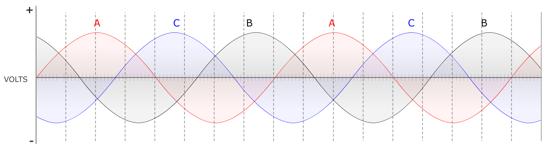
The image below shows an A-C-B system, or a C-B-A system, or a B-A-C system, depending on the reference.
What is the Best Way to Communicate Phase Sequence?
There are two rules you should use whenever communicating phase sequence, or phase rotation, information:
- Always use the voltage designations.
- Always start with the same designation.
If you always follow these two rules, there shouldn’t be any communication errors.
If you want more information about what we’ve discussed so far, you should check out our Online Course 1-1: The Three-Phase Electric Power System (4 NETA CTDs).
Determine Phase Rotation via Phasor Diagrams
There is still a problem that I find in most of my classes…phasor rotation is NOT depicted by waveform drawings; they’re depicted in phasor diagrams. Many of my students can’t determine the correct rotation with typical phase rotation notations on a drawing like the following:
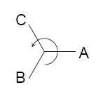
Let’s test your knowledge. Which phase rotation is the following drawing?
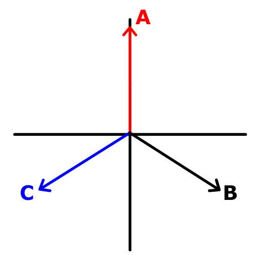
The phase rotation is A-B-C.
You can’t determine phase rotation with a phasor diagram unless you know the one universal rule in the relay testing world. ALL PHASORS ROTATE COUNTER-CLOCKWISE.
The video below shows you how the waveforms and phasors inter-relate.
Notice that the phasors rotate counter-clockwise and that the corresponding waveforms match the A-B-C rotation from the waveform drawings earlier?
There should always be an arrow indicating the direction that the phasors are rotating and it should always be pointed counter-clockwise.
Which rotation is the phasor diagram below?
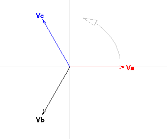
It is still A-B-C rotation. You can always tell rotation by imagining that the phasors are spinning like this video below.
If you want to be sure you understand phase rotation correctly, put your finger anywhere on the phasor diagram and imagine that the phasors are spinning counter-clockwise. Start paying attention when your reference phasor crosses your finger. Which phasor crosses your finger next? Which is the last phasor to cross your finger? This will help you determine the phase rotation as shown in the following video:
Let’s try another test!
Which phase rotation is being generated in the following drawing?
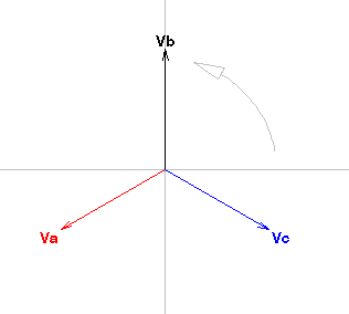
It’s A-B-C again as per the following video:
Now that you know what to look for and how to determine the phase rotation,
Can You Determine the Phase Sequence Using Phasor Diagrams?
What is the phase rotation using 1 as a reference in the drawing below?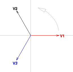
The phase rotation is 1-3-2 as per the following video:
You should be able to reliably determine the phase rotation of a system and to communicate that information effectively to someone else. The results can be catastrophic if you can’t, which is why this a vital skill all relay testers should know.
You can get more information about phasor diagrams with our Online Course 1-2: Phasor Drawings for Relay Testers (4 NETA CTDs).
You can get more information about how phase rotation applies to relay testing in future posts, or in our How to Test Protective Relays Online Seminar (16 NETA CTDs).
You can get more information about all of our courses here.
I hope you found this post useful. Please click one of the buttons below if you did, or drop a comment. I read every comment you submit.
Discover more from Valence Electrical Training Services
Subscribe to get the latest posts sent to your email.
Did you like this post?
You can share it with these links:
Read More Articles:
Coming Soon! The Relay Testing Handbook: Simplified Motor Protection Relay Testing
It is a very good explanation; can you please send me an PDF file about the phase rotation topic? I appreciate in advance your kind contribution to this important topic.
We don’t have a pdf for this post. It’s explained in detail in the online course.
My case is this, I got a 3 phase running into a building, the phases are not labeled. How can I identify which is A-B -C or R,S T?
The designations are up to the site. You can call each phase whatever you want in any order. The key is to be consistent.
Some substations designate the breaker poles connected to a direction as A phase, then B, then , or A then C then B.
Some sites use the manufacturer designations on the circuit breaker (Poles 1&2 are A-Phase, 3&4 B-Phase, and 5&6 are C-Phase).
Some sites look at the front of the switchgear and say A-B-C or A-C-B should be left to right.
The phase designations and order can change depending on where you are on the site, like Grand Coulee Damn where one power station is A-B-C and the other is A-C-B.
If you want to understand and confirm the phase rotation on a site, you have to:
1. Pick a convention (A-B-C, R-S-T, etc.),
2. Decide what system you will use to define the phases (Map Directions, left to right while facing x, pole designations, etc), and
3. Pick a reference (what phase and designation will be zero degrees.)
whats the correct rotation ? of 3 phase air condition compressor . there is alable on the compressor connect in to proper rotation is it right rotation or left rotation
The correct rotation for a motor depends on the motor and its connections.
There will be an arrow on the shaft, or one end, telling you which way it should turn; and the nameplate will tell you how to connect it.
Once its connected, bump the motor when it is uncoupled to make sure it is turning in the correct direction.
Interesting topic
Can you supply a diagram on how to phase in 11kV feeders using phasing sticks.
We focus on relay training.
There is a device to determine the phase I.D. with respect to a known grid phase. The PhaseTrakker from EDM, International in Ft. Collins, CO.
Mr Cris, really great way of explaining concept and best presentation, specifically addition of video. If anyone need to understand this topic or relay training, I think you are best.
Thanks for the kind words.
Dear Chris, which standard/ Code like IEEE/ IEC/ NEC specify standard phase sequence and marking right to left or left to right for US and EU ?
There is no standard that I’m aware of.
Thank you for your article. It is very informative. I have a situation that I would like to get an expert opinion on. Would you be willing to assist me with this?
Thank you,
Cathy Howell
Thanks for the kind words.
You can ask questions here https://relaytraining.mystagingwebsite.com/electrical-test-questions/
Thank you for including so many examples to test my knowledge! Though I am an electrical engineer who has been in the industry for years, this is a concept I never felt I mastered. This has been very helpful.
In my opinion, this post should be kept and shared as long as the three-phase system remains the standard for most commercial and industrial uses worldwide.
Chris,
I really enjoyed your post. It is very well put together – thank you for sharing. Unless I missed it, the post did not directly address one scenario that comes up fairly often: when an electrician connects a rotation meter (such as a Sperry PSI-8031) on a 3PH3W system rotating A-B-C CCW, will the rotation meter rotate CW or CCW? Assume the electrician has connected the rotation meter correctly: Red lead to A phase, White lead to B phase, Blue lead to C phase.
Clockwise and counter-clockwise are a pet peeve of mine because the terminology is completely subjective. In North America, the standard motor connections were defined so the motor would rotate counter-clockwise if connected to an A-B-C system. So a meter like that would display Clockwise if connected to an A-B-C system in North America.
I haven’t touched a meter like that in 25+ years, so I’m not sure what the standard is now, or whether it is an international standard. Your results may vary.
Chris, regarding my question, you were right about what the rotation meter would show…clockwise for an electrical system rotating CCW-ABC. I have a video showing voltage vectors out of a relay test set and the rotation meter doing it's thing, but I don't see a way to attach it.
Good to hear I was right :)
Very rich information , its very worth if you could give ability to download videos and content. we need realy to present it to our team under your right information ..
Thanks for the kind words.
You can download all the videos and content on this post.
Thank you. Easy to understand, very useful. Please send me this article on understanding phase rotation.