Temperature Relays from 1924 Silent Sentinels
Silent Sentinels 1924 Excerpt #14
This excerpt from the 1924 version of Silent Sentinels discusses the most common temperature relays used in the early days of electrical systems. This is the 14th in the series. Follow these links to learn more about this series and the 1924 version of Silent Sentinels.
Westinghouse Protective and Control Relays
3-Temperature Relays
Type HM Bearing Thermostat Relays
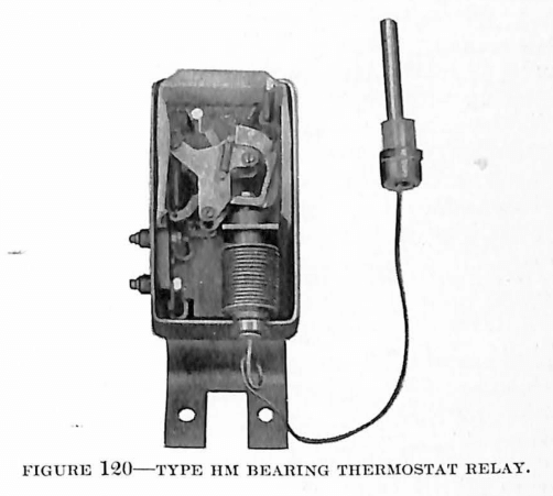
Type HM relays are designed for use in protecting the bearings of rotating machinery from the disastrous effects of over-heating. With this relay installed, it is unnecessary to have constant supervision of the bearings of rotating machinery. This relay is particularly valuable in automatic substation work.
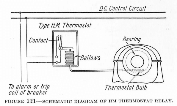
The action of the thermostat is largely mechanical. It consists of the operation of a toggle switch by means of the expansion of a bellows. The thermostat unit consists of a bulb which is to be embedded in the bearing, the connecting tube, and the expansion bellows. As the temperature of the material in which the bulb is embedded rises, the liquid enclosed in the bulb and bellows volatizes, and thus creates a pressure, causing the bellows to expand lengthwise. This expansion serves, in turn, to operate the toggle switch, thereby closing the contacts of the relay.
The relay usually is made to operate at 100 degrees, but different thermal elements, having the temperature of operation 70 degrees, 90 degrees or 100 degrees Centigrade, may be supplied.
Type HN Grid Thermostat
A slight modification of the HM thermostat is used for the protection of grid resistors from damage, due to overload or to sustained short circuits on the system. The construction of this relay is largely the same as the HM with the exception of the manner of resetting. This HN relay resets automatically, whereas the HM relay has to be reset by hand. The thermal element supplied with the HN relay is also somewhat different, giving operation at either 150 degrees Centigrade or 300 degrees Centigrade.
Type CT Temperature Relay
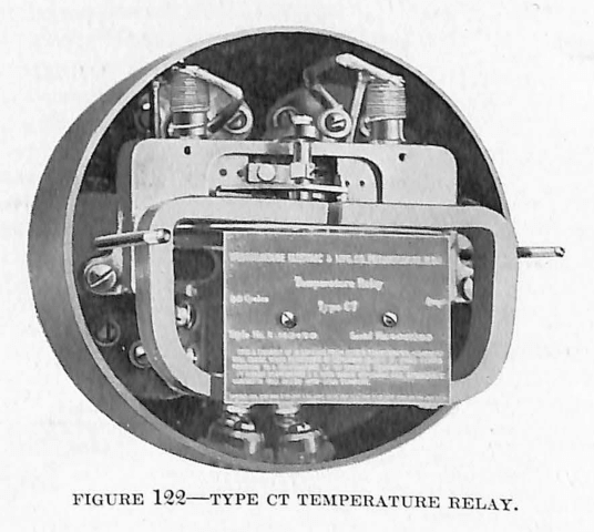
The problem of protecting electrical apparatus against over-temperature presents many difficulties. The object in any such protective apparatus is to allow the protected machine to remain in service as long as it is safe to do so, and yet to disconnect it from the source of power as soon as the temperature becomes unsafe for further operation. In order to obtain the most efficient protection, a relay used for this purpose must take into consideration the ambient temperature, the speed with which the windings of the apparatus heat up when subjected to overload, and the conditions existing when the temperature of the machine becomes dangerously high.
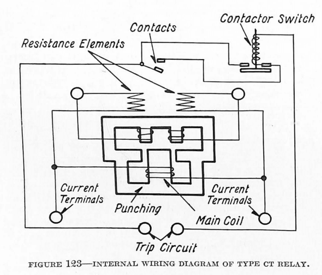
The CT temperature relay is applicable on alternating-current circuits where the apparatus is so arranged that exploring coils can be installed in the windings. It operates on the Wheatstone Bridge principle, the moving part operating on the induction principle. The relay in its appearance is similar to the type CO over-current relay. The lower coil is directly connected to a current transformer in one lead of the machine which is to be protected. The upper coils are connected across the two points in the bridge arrangement to which the galvanometer is ordinarily connected. Two permanent resistance units mounted in the relay case serve for two arms of the bridge, while two copper exploring coils, embedded in the winding of the apparatus to be protected, serve for the other two arms.
The points of the bridge opposite those connected to the upper coils are connected to the current transformer in parallel with the lower coil of the relay. The resistances of the different arms of the bridge are so arranged that at normal operating temperature no current flows through the upper winding of the relay. When the apparatus becomes heated, however, the resistance of the arm formed by the exploring coils changes, thus destroying the balance and causing current to flow through the upper coils of the relay. This produces a torque tending to rotate the discs and to close the contacts. As it is necessary to have a certain quantity of current flowing in both the upper and lower coils of the relay before the disc will rotate to close the contacts, the operation of the relay depends upon three conditions:
- The temperature of the material surrounding the coils must be such as to cause an unbalance sufficient to send current through the upper coils of the relay.
- The current flowing in the line at that time must be such as to give a sufficient current value in the lower coil of the relay.
- Heat that has been generated in previous overload, but that has not yet been dissipated, tends to influence the temperature of the exploring coil.
Type DT Temperature Relay
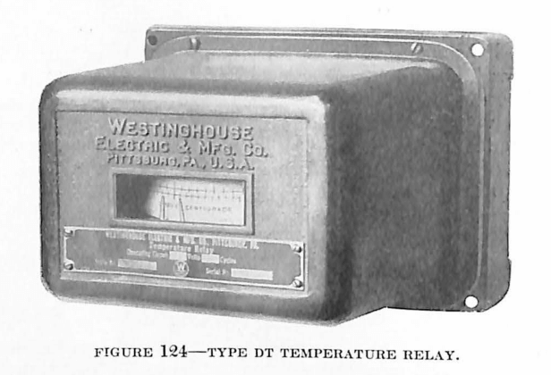
The DT temperature relay is simply a modification of the D overcurrent relay used in connection with a Wheatstone Bridge. Its use is similar to that of the CT relay, except that the DT depends altogether on direct current for its operation, and does not take into consideration the current flowing at the time when the critical temperature is attained. As in the case of the CT relay, the operating coil replaces the galvanometer connection in the bridge circuit. The two opposite points of the bridge are connected across a constant direct-current source of voltage. Three arms of the bridge are made up of fixed resistance, while a fourth arm consists of a copper exploring coil embedded in the winding of the apparatus to be protected.
The resistance values of the arms of the bridge are so proportioned that when the temperature of the apparatus reaches a safe operating point there is no appreciable current flowing through the relay moving coil winding. With a low temperature in the winding of the apparatus, current will flow through the relay coil in one direction, and with a high temperature current will flow in the other direction. Thus with low temperature, contact is made in one direction, while with high temperature contact is made in the opposite direction. From this it is evident that the operation of the relay depends solely on the temperature of the windings in the apparatus, leaving out the consideration of the current drawn by the apparatus at the time the critical temperature is reached. This relay, therefore, is applicable wherever a constant source of direct-current voltage is available and where the load conditions may be disregarded.
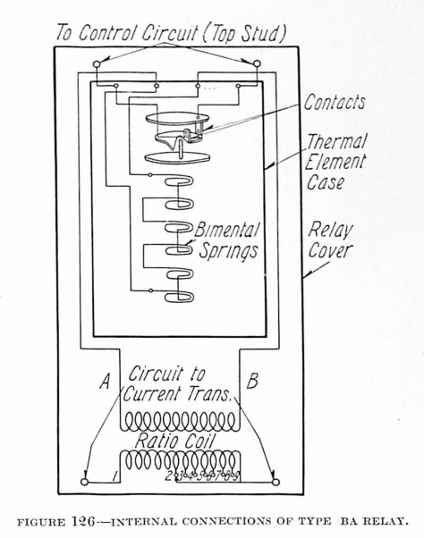
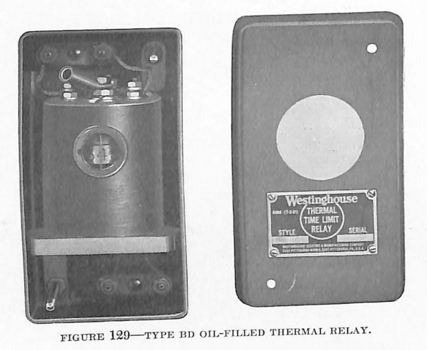
Type BA and BD Oil-Filled Thermal Relays
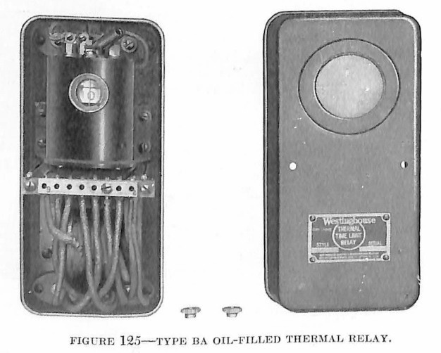
Another type of temperature relay which does not require the use, of exploring coils embedded in the windings of the apparatus to be protected has been developed. This type depends upon the expansion of a bi-metal element. The element has characteristics such that it heats up at the same rate as the windings of the apparatus to be protected. In order to further duplicate the temperature rise of the protected apparatus, the bi-metallic element is immersed in oil and the walls of the container are such that the dissipation of heat will be, approximately, the same as in the case of the apparatus to be protected. The operation of the relay is simple. When the bi-metallic element heats to a certain temperature it expands sufficiently to operate the relay, closing its contacts.
The BA relay is suitable for use on alternating-current circuits.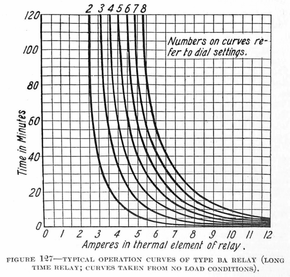
The BD relay is suitable for use on direct-current circuits. It is similar to the BA relay in construction and operation.
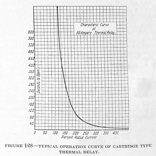
A cartridge type of relay which is not oil-filled is made suitable for either alternating-current or direct-current application, where high precision is unnecessary. The operation of the cartridge type relay is dependent on the expansion of a bi-metallic element in the same way as that of the BA and BD relays, except that precautions are not taken in the relay to have its temperature rise identical in degree with that of the rise in the protected apparatus.
Discover more from Valence Electrical Training Services
Subscribe to get the latest posts sent to your email.
Did you like this post?
You can share it with these links:
Read More Articles:
Auxiliary Relays from 1924 Silent Sentinels