Please Explain the Principle of Weak InFeed Echo Permissive Over Reach Transfer Trip Schemes?
Rahim submitted this question to the Ask Chris section of the RelayTraining.com website.
Most line distance protection schemes assume that the system will always be able to supply enough amps to make the relays trip. However, there are many scenarios on transmission systems across the world where you could have a strong source on one end of a transmission line with a weak source on the other, and this configuration could prevent the protective relay(s) from operating the way we would expect them to.
The scenario that is easiest to understand, and explain, occurs when we connect a generating plant, or generator, to the transmission system. The drawing below shows this scenario with the generator breaker open and a fault on the transmission line close to BKR1.
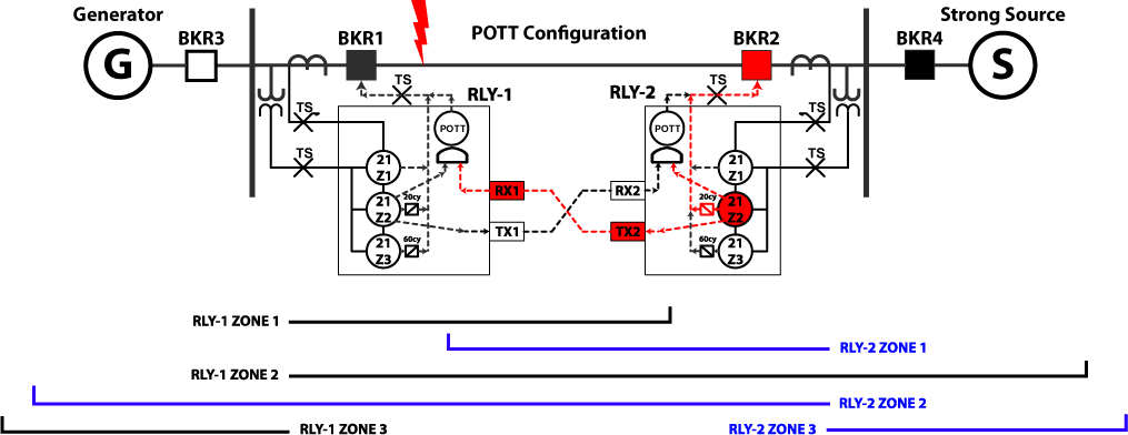
If this was a normal system, RLY-2 would:
- see a Zone 2 (Z2) fault,
- send a Z2 Permissive Trip,
- receive the Permissive Trip from the other side, and
- open BKR2 after a short time delay.
RLY-1 would:
- see a Zone 1 (Z1) and Zone 2 fault,
- send a Z2 Permissive Trip, and
- open BKR1 instantaneously.
We are simulating a weak infeed from the generator by opening BKR3 which means that RLY-1 does not see the fault and does nothing while RLY-2 opens BKR2 after the normal time delay for Zone 2. (around 20 cycles)
This is not an ideal situation. There is a fault on the line and BKR1 is still closed. If we bring the generator up to speed and close the generator breaker, we will close the generator onto a fault. The fault was also connected to the system for 20 cycles, which was plenty of time to cause an unnecessary disruption to the system. We have the technology to do better, and a Weak Infeed protection scheme can open BKR1 when a fault occurs on the line, and speed up the trip time of BKR2.
We need RLY-1 to recognize that there is a fault on the line, even if the generator breaker is open. Fortunately, there are numerous ways for relays to communicate information about a fault. The first method uses the generator breaker’s (BKR3) 52a contact. We know that the left side of the circuit in our example is guaranteed to be weak if BKR3 is open, so we can create an “Echo” permissive signal that sends a permissive trip to RLY-2 when RLY-1 receives a permissive AND the generator breaker is open as shown in the drawing below.
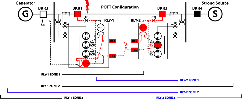
The fault hasn’t changed since the first example, but both breakers opened after a very short time delay with the new Weak Infeed logic. In this scenario, RLY-2 would:
- see a Zone 2 fault, and
- send a Z2 Permissive Trip.
RLY-1 would:
- receive the Permissive Trip from the other side,
- see that BRK3 is open,
- send a permissive Echo to RLY-2, and
- open BKR1 based on the Weak Infeed logic.
RLY-2 would:
- receive a permissive echo from RLY-1,
- still see Zone-2, and
- then open BRK2 based on a permissive trip instead of waiting for the Zone-2 time delay.
This system works great when BKR-3 is open, but generators typically do not have a lot of fault capacity compared to the system. The generator side could still be considered weak when the breaker is closed because of its relatively weak ability to contribute to a fault. We would be right back at square one if this was the only aspect of Weak Infeed protection schemes, and the generator breaker was closed.
Generator protection schemes can’t use traditional inverse time overcurrent (51) protection because generators can’t produce enough fault current to make them effective. Some generator relays do use modified 51-elements for system backup protection by applying what we’ve learned about faults over the last 100 years or so. Everyone knows that a fault will cause the measured current to increase in proportion to the severity of the fault, but that doesn’t happen in isolation. The faulted voltage is also affected.
What happens to the faulted voltage during a fault?
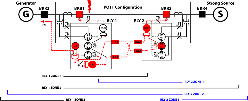
The faulted voltage will decrease. The actual fault voltage will be proportional to the distance from the potential transformers (PTs) the relay uses to measure the system voltage. The fault voltage will be zero if the fault is on top of the PTs, and will grow as the fault gets farther away. Therefore, we can set an undervoltage element to operate if the voltage drops enough to signal a fault that is closer to the weak side. That undervoltage can be added to the Weak Infeed logic as shown below.

The fault hasn’t changed since the first example, but both breakers opened after a very short time delay with the new Weak Infeed logic even though the generator breaker is now closed. In this scenario, RLY-2 would:
- see a Zone 2 fault, and
- send a Z2 Permissive Trip,
RLY-1 would:
- receive the Permissive Trip from the other side,
- recognize that a fault is on the line because the Undervoltage (27) element operated,
- send a permissive Echo to RLY-2, and
- open BKR1 based on the Weak Infeed logic.
RLY-2 would:
- receive a permissive echo from RLY-1,
- still see Zone-2, and
- then open BRK2 based on a Permissive trip.
We now have a flexible solution, but have introduced a new problem. What will happen if the fault is on the generator side?

BKR1 and BKR2 would both operate because none of the conditions in our Weak Infeed logic have changed. We need a way to block the infeed logic when the fault is not on the protected transmission line. Can RLY-1 tell whether the fault is on the line, or behind RLY-1 near the generator?
The Zone-3 protection element is set to detect faults behind the relay, and we need to add it to the Weak Infeed protection scheme to prevent the Echo signal from being sent if the fault is behind the relay as shown in the following diagram.
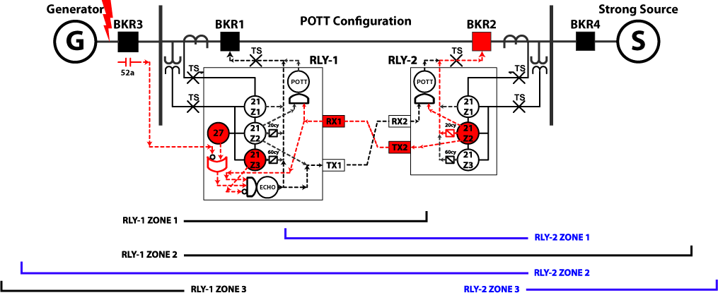
In this scenario, all of the previously described components are in place, which means the Weak Infeed logic would normally send an Echo signal, but the relay’s Zone-3 element has picked up and prevented the Echo permissive from being sent. This new piece to our logic scheme now prevents the Weak Infeed scheme from operating for faults that are not on the transmission line. Some engineers try to make it even more secure by adding a Zone-2 block for Weak Infeed logic as well.
If we move the fault back onto the line, Zone-3 does not pickup and the Weak Infeed Echo protection scheme works normally.
These are the basic essentials of Weak Infeed Echo Permissive Protection schemes. I hope I was able to answer Rahim’s question adequately. Please feel free to comment below if you have more questions about this scheme, or have something new to add.
Share the Knowledge
Please share and like this post if you liked it. It helps us get noticed, which means we can keep offering free content like this.
Have a burning question you want answered? Go to the Ask Chris form and I might have an answer for you!
Discover more from Valence Electrical Training Services
Subscribe to get the latest posts sent to your email.
Did you like this post?
You can share it with these links:
Read More Articles:
Valence will be at the NETA PowerTest 2015 Conference in Nashville, TN
This Explanation was usefull, that made me understand the POTT and Echo POTT thoroughly.. Thanks for this beautiful explanation
That is a brilliant explanation and the protection scheme diagrams are very good. Thanks and keep up the good work.
your excellent answer is very appreciated , thank you for this effort
I understood the PUTT scheme clearly although POTT scheme is confusing little.
When we have to select POTT scheme instead of PUTT scheme.
Why PUTT scheme send Z2 pickup to remote end while local breaker is tripped by Zone-1 pickup.
Thanks for the comment.
PUTT schemes share Zone 1 and Zone 2 information back and forth as described here PUTT Scheme video
POTT Schemes share Zone 2 information as shown at the end of this video
The scheme in this article uses a POTT scheme.
Hi, thanks for the explanation. If the fault is located near to the highest infeed, how is going to work Pott with the weak infeed principle? And how it work the underreaching with extended zone scheme with the weak infeed principle? Thanks you and sorry for the grammatical mistakes, I’m still learning English.
Thanks for the clear explanation. It fully explains the principle.
very helpful explanation. You fully and clearly described different types of pilot schemes. thank you for the effort
Thanks!
Very Very thanks for your
I hope more meeting at your web
Thank you Mr Chris for a this simple and clear presentation of this subject matter. Kudos to you once again.
Very useful, diagrams are clear, Thanks
If fault occurs between Generator and Breaker 3 reverse looking element Zone 3 is picked up which blocks echo trip being sent back to strong source Breaker 2 and trip will not take place. Please send modified diagram. S.Vasudevan 9840229620 Ex. ABB Site Manager and Testing and Commissioning engineer with 52 years service
Thanks for your comment, but I do not know what you are referring to. Can you be more specific.
It is assumed that Generator protection works to trip Breaker 3 and current is zero and no trip of breaker 1 or 2.
Please quote the exact part of the post you don’t agree with and why you don’t agree.
If a fault occurs between the Generator and Breaker 3 as you suggest, you are correct in that the Zone 3 of Relay 1 will see this in the reverse direction and block a “Weak infeed echo”.
This is what is suppose to happen, as the fault is in the Generator zone of protection, and we do not want relay 2 to accelerate its Z2 timer for a fault outside the line zone.
If the Generator protection then fails to clear this fault by opening CB3, then relay 2’s Zone 2 timer (20 cycles) times out and clears the fault.
The I/T receive at Relay 2 simply accelerates a Zone 2 for a genuine in zone line fault (POTT Scheme).
The lack of an I/T receive does not restrict Relay 2 Zone 2 element from operating normally.
This is very high knowledge applied to POTT Schemes; thank you so much for sharing it!
Thanks for the kind words.
Thank you so much for creating this explanation.
Can I ask you two questions?
First, why if a fault near the BKR1 then RLY-1 is not pick up? Whether 50 elements are not enough current to pick up (i.e., 50FP setting of SEL421 relay)?
Secondly, what happens if BKR3, BKR4 trip while BKR1 is still open other than BKR2 trip with delay time 20 cycles?
Many thanks.
There is no current flow in Circuit Breaker 1. BKR3 is open.
The other two breakers should only trip for faults in their zone of protection or as backup protection for 1 & 2 if they fail to clear the fault.
Can you please explain in the line parameters what does it mean by CT Star point : towards the line
It’s a standard for CT connections that you’ll typically find outside of North America (EU) that means the starpoint of the CT is on the side of the CT where the protected device lies. North Americans (NA) typically use some form of “Polarity marks face away from the protected device” instead because the non-polarity mark sides of the CTs are usually connected together. Both represent the same standard connection for CTs connected to a relay.
A generator relay protects a generator, so the relay in the diagram below is looking for forward current from the neutral to the generator.
All three connections are correct because any current flowing into the generator will flow into the odd terminal numbers.
The connection in the middle follows the EU standard because the starpoint of the CTs is on the protected device side of the CT (towards the line). The polarity marks also follow the NA standard because they are on the opposite side. This would be the normal connection you would see on most drawings and its easy to see that the current flowing into the generator is also flowing into the odd terminals on the relay
The first connection on the left is a non-standard connection because the polarity marks face toward the protected device and the star point of the CTs is on the opposite side. But it still works because the CT sides facing away from the generator is connected to the odd terminal numbers.
The connection on the right follows the EU standard because the starpoint of the CTs is on the protected device side of the CT (towards the line). However, the polarity marks are facing towards the protected device, so this connection does not follow the NA standard. In the end, it doesn’t matter because the current flowing into the generator is also flowing into the odd terminals on the relay and this connection will work fine.
Very helpful and very clear
hey i am finding tough to understand current reversal concept in pott schemes, my questions are
1. when and why current reversal will occur
2. how we can avoid them in settings or any other way, what is the basic behind current current reversal
This video may help answer your questions.
https://relaytraining.mystagingwebsite.com/understanding-permissive-over-reaching-transfer-trip-pott-communication-assisted-trip-schemes-video/