How to Perform an In-Service Protective Relay Meter Test
In-service protective relay meter tests are THE MOST important tests that should be performed on every digital relay. All of your offline relay testing is meaningless if:
- The CT/PT ratios are incorrect.
- The relay isn’t connected to its input signals (CTs/PTs).
- The relay is looking in the wrong direction.
- The phase rotation is backward.
Offline relay testing cannot prove any of these issues with 100% certainty, and the relay is effectively disabled if any of the last three items are incorrect. What do relays do for most of their lifespan? Nothing. What does a relay do if it is disabled by one of these problems? Nothing! If you turn it on and nothing trips, that does NOT mean it is working correctly.
Online meter testing is the ONLY way you can make sure the relay is correctly connected to the power system, and this post will help you perform an effective meter test.
The first problem that many relay testers have when performing an in-service meter test is the built-in ambiguity of not controlling the inputs. An offline meter test is easy: Apply a value, and the relay should report exact magnitudes and angles within tolerance. You do not get to apply fixed values during an in-service meter test, so you have to use some electrical common sense.
The “How to Measure Phase Angles with a Phase Angle Meter” post showed you how important the reference is when measuring AC systems. Remember that the A-Phase voltage is usually the reference in most relays when performing in-service meter tests. Let’s take that knowledge with some basic electrical theory to see how it applies to the power system.
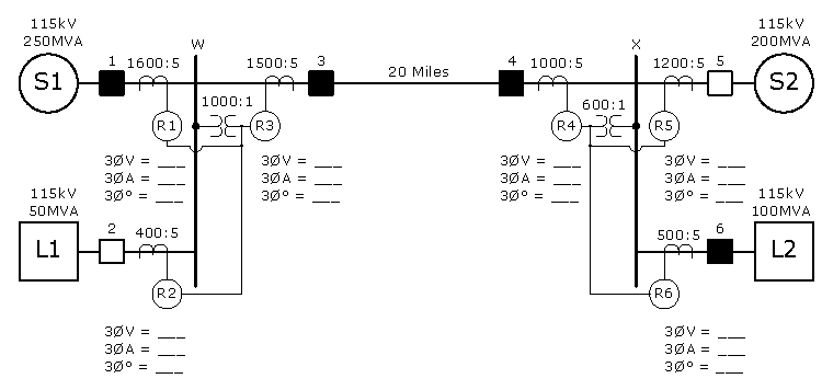
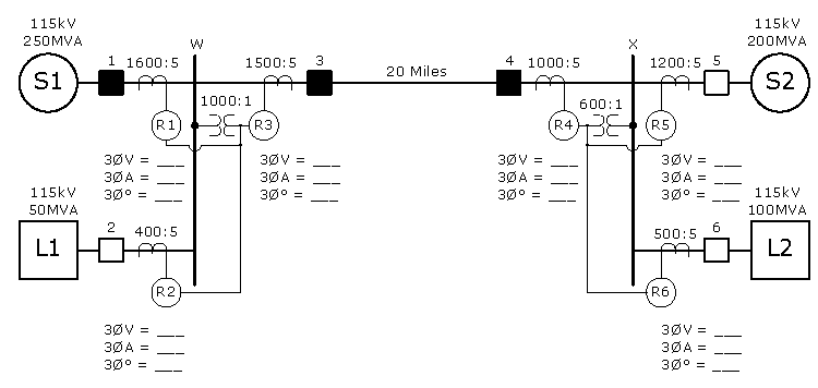
The power system below can give us different scenarios. Try to reason out what each relay will measure using the following parameters:
- This is a three-phase balanced system.
- Use the lagging angle system used by all relay testing software in their fault modes. (Also used by RTS, Megger, GE SR, etc.)
- Breakers #1, 4, 3, and 6 are closed.
What will each relay measure in this system if you were to perform an in-service protective relay meter test?
Don’t look at the answers beforehand. A good relay tester should be able to predict the general idea of what will happen in each scenario. Being able to figure out what’s going on will help you become a better relay tester.
Here’s how I would break the problem down:
First, we have to determine the flow of current and system parameters. The source connected to Breaker 1 supplies the voltage for the system. The load determines how much current will flow, which means current will flow from Breaker 1 to Breaker 6 through Breakers 3 and 4.
The amount of current that flows in the system is always determined by the load. You can calculate how much current (502.04A) is flowing through the system using the standard 3Ø power formula (3Ø Amps = MVA / (Sqrt(3) * P-P Voltage).
All the relays use their AØ voltage as their reference, so the voltage angle in all relays will be 0°.
We can assume that the current will lag the voltage because normal loads have inductance. If a significant amount of current is flowing in a system, inductance will exist because:
- AC current flowing through a conductor creates a skin-effect, or self-inductance.
- AC current flowing through parallel conductors creates mutual inductance. (That describes every three-phase system.)
- The line capacitance on a short line (<50 miles or 80km) is negligible. The line in our example is only 20 miles long.
This means the load is almost guaranteed to have an inductive component, even if it was 100% heaters and light bulbs. Did you know that motors used 23% of all electricity consumed in the United States in 2005? That’s another reason we can assume that any random load will be inductive; motors are inductive machines, and they are a large part of the electrical system.
These principles suggest that any load current flowing toward a load will lag the voltage by 1° to 30°. Why 30°? Because most motors have a minimum efficiency of 86%, or power factor of 0.866 Lag. This translates into a current that lags by 30°(Cos-1 (0.866) = 30)
Here are the answers for a perfect world with nominal voltage:
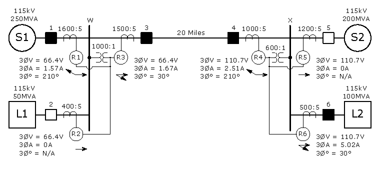
Relays #1, 2, and 3 will record approximately 66.4V because they are connected to the 1000:1 PT circuit.
Relay 1 will record 1.57A (502.04A/1.57A = 1600A/5A), and all three currents will lag their voltages by approximately 210°. Why 210°? Because Relay #1 protects the power system from faults on the line between Buss W and Source S1. Therefore, Relay 1 defines Forward as current flowing from Buss W to Breaker 1. We can assume the current flowing into the load is somewhere between 0° and 30°, and choose 30° as the worst case scenario. That current is flowing through Relay 1 in the opposite direction, so Relay 1 will measure 30°+180°, or 210°.
Relay 2 will record zero amps because its breaker is open.
Relay 3 will record 1.67A (1.67A/502.04A = 5A/1600A), and all three currents will lag their voltages by approximately 30° because the current is flowing from S1 into the transmission line from Breaker 3 to 4. This is Relay 3’s Forward direction.
Relays #4, 5, and 6 will record approximately 110.66V because they are connected to the 600:1 PT circuit.
Relay 4 will record 2.51A (502.04A/[1000A/5A]), and all three currents will lag their voltages by approximately 210° because the current is flowing from S1 into the transmission line from Breaker 3 to 4. Relay 3 only records a Forward direction when current flows from Breaker 3 to Breaker 4.
Relay 5 will record zero amps because its breaker is open.
Relay 6 will record 5.02A (502.04A*5A/500A), and all three currents will lag their voltages by approximately 30° because Relay 6 protects the L2 equipment from damage. Current is flowing into L2, so Relay 2 measures the current flowing in the Forward direction.
The key to this kind of analysis is that you need to know:
- That current flows from a source to a load.
- The location of sources and loads in the system.
- That almost all loads will have lagging angles.
- The relay’s A-Phase voltage will almost always be 0°.
- Which direction the current flows through the system.
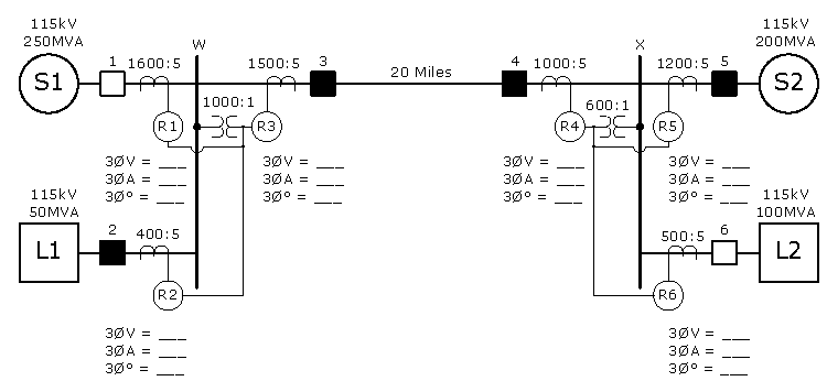
What would each relay measure during an in-service protective relay meter test after closing Breakers 2, 3, 4, and 5 instead?
Here are the answers for a perfect world with nominal voltage:
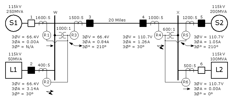
Relays #1, 2, and 3 will record approximately 66.4V because they are connected to the 1000:1 PT circuit and the nominal voltage hasn’t changed.
Relay 1 will record zero amps because its breaker is open.
Relay 2 will record 3.14A (251.02A/3.14A = 400A/5A), and all three currents will lag their voltages by approximately 30° because the current is flowing into the load, which Relay 2 considers to be in the Forward direction.
Relay 3 will record 0.84A (0.84A/251.02A = 5A/1600A), and all three currents will lag their voltages by approximately 210° because the current is flowing from S2 into the transmission line from Breaker 4 to 3. This is Relay 3’s Reverse direction.
Relays #4, 5, and 6 will record approximately 110.66V because they are connected to the 600:1 PT circuit and the nominal voltage hasn’t changed.
Relay 4 will record 1.26A (251.02A/[1000A/5A]), and all three currents will lag their voltages by approximately 30° because the current is flowing from S2 into the transmission line from Breaker 4 to 3.
Relay 5 will record zero amps because its breaker is open.
Relay 6 will record 5.02A (502.04A*5/500), and all three currents will lag their voltages by approximately 30° because Relay 6 protects the L2 equipment from damage. Current is flowing into L2, so Relay 2 measures the current flowing in the Forward direction.
The voltages are the same for this scenario, but the currents have changed direction.
What would each relay measure during an in-service protective relay meter test after closing Breakers 1, 3, and 4?
Here are the answers for a perfect world with nominal voltage:
This situation is very different because there is no load connected to the generator. The generator will continue to generate a voltage, and there could be some current caused by the capacitance of the transmission line. This often means that we can’t perform a meter test because the current is too low to measure and all the inaccuracies will add to create an unreliable measurement. You can usually tell when you don’t have enough current to measure when the phase angles appear to be all over the place.
Never trust current measurements less than 0.25A secondary.
However, you can get accurate measurements if the line is long (>50 miles or >80km) and/or the voltage is high (>230kV).
What would each relay measure during an in-service protective relay meter test after closing Breakers 1, 3, and 4 with a higher system voltage?
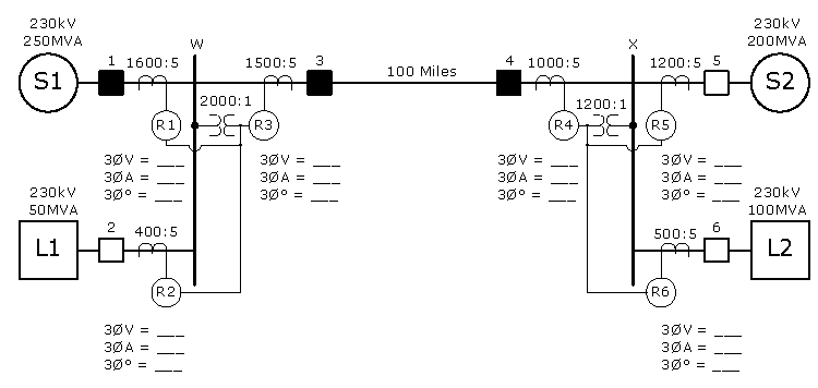
Here are the answers for a perfect world with nominal voltage:
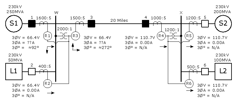
Relays #1, 2, and 3 will record approximately 66.4V because the nominal voltage and PT ratio doubled.
Relay 1 will record some amps because its breaker is closed. The transmission line is the load, and it should be close to a perfect capacitor, which means the current flowing into the transmission line should lead the voltage by nearly 90°. If we assume it leads by 88°, Relay 1 will measure 92° lag because the current is flowing in the opposite direction of Relay 1’s Forward designation.
Relay 2 will record zero amps because its breaker is open.
Relay 3 will record some current, and all three currents will lead their voltages by approximately 88° because the current is flowing into the capacitive transmission line, which Relay 2 considers to be in the Forward direction. The relay will measure 272° using the lagging angle system.
Relays #4, 5, and 6 will record approximately 110.66V because they are connected to the 1200:1 PT circuit and the nominal voltage and PT ratio both doubled.
Relay 4 will record zero amps because the transmission line is the load and there is no source connected to Relay 4 to supply that load.
Relay 5 will record zero amps because its breaker is open.
Relay 6 will record zero amps because its breaker is open.
What have we learned about in-service protective relay meter tests?
You can apply some common sense to perform an in-service meter test when you know where the loads and sources are, such as:
- Any site that doesn’t have a generator (refinery, institution, factory, etc.). The current will always flow from the source to the loads.
- Any site with a generator when the generator is offline. Current flows from the source to the loads.
- Any site that is only supplied by its local generator. Current flows from the generator to its loads.
- Generator plants when the generator is offline. Current flows from the utility to station service.
- Generator plants when the generator is under load. Current flows from the generator out into the system.
Once you know which direction the primary current is flowing, use the tools described above to:
- Make sure the CT ratios are set correctly in the relay.
- Make sure the PT ratios are set correctly in the relay.
- Make sure the relay is detecting current flow in the correct direction.
This test becomes much more difficult in a typical substation when you can’t control the source and load. In these cases, you must look at all the feeders to determine where the current is flowing to determine which direction the primary current is flowing. You could also contact your system control, or distribution center, to help determine where the current is flowing.
This post covered the first three problems that can disable a relay, but there is still one more problem that needs to be looked at to make sure the relay is fully functional. Look for the next post on sequence components that will show you how to make sure the phase rotation injected in the relay matches the relay settings.
Don’t forget to have fun out there!
Discover more from Valence Electrical Training Services
Subscribe to get the latest posts sent to your email.
Did you like this post?
You can share it with these links:
Read More Articles:
Understanding Permissive Over-Reaching Transfer Trip (POTT) Communication Assisted Trip Schemes Video
It is rare operators and maintenance personnel check the relay meter; they are afraid to “touch” the buttons. If they do it regulary , many problems could be avoid.
Thank you Chris. Very very useful. Only some minimum details. For the “answer for a perfect world” of the first example, for the relay 4 says “… Relay 3 only records a Forward direction when current flows from Breaker 4 to Breaker 3.” and i think it should says ” … Relay 4 …”. In the last question, the figures have a different PT relationship. The correct PTR are 2000:1 and 1200:1 on the 230 kV busbars.
Sorry for my english.
Thanks for commenting. I corrected the first problem.
The PT ratios doubled because the voltage doubled, which means the coltages will be the same as the previous questions. It does state that in the post, so I’m not sure what you are referring to.
Thanks Chris, that’s right, the transformation ratio of the PTs is fine because the voltage is 230 kV, what I’m referring to is an error in the drawing that appears before the answer of the last question. you can see, RTP of 1000: 1 and 600: 1 are indicated in the initial figure (although 230 kV bars are already indicated), however in the drawing that appears when opening the answer the RTP have changed to the correct values of 2000 : 1 and 1200: 1.
I see now. Yes, you are correct. Should be fixed now.
Thanks!
How did you calculate the 502.04A load current. I keep getting 1255.15 Amps.
Thanks for your question. The formula for VA in a three-phase system is VA = square root of 3 x P-P Voltage x Amps. 100,000,000 = 1.732 x 115,000 x A rearranged is A = 100,000,000 / (1.732 x 115,000) = 502.058 Primary Amps with a 500:5 CT ratio.
This exercise if very instructive, but I must be very dense or missing something really obvious, or both.
For the first example: Why is the voltage at Relay 1 = 66.4V?
With a 1000:1 PT, the ratio is 1000, so 115,000V/1000 = 115V?
You are missing something obvious, which is also the most common mistake.
The system is rated P-P and most line relays use P-N voltages.