What is DC Offset? Ask Chris
I was recently asked about DC Offset during a paper I presented at the 2015 Hands-On Relay School and struggled with an answer because I know what it looks like and I know it exists, but I’ve never heard an explanation that made sense to me. The answer you usually get sounds something similar to, “The amount of offset depends on the X/R (power factor) of the power system and the first peak can be as high as 2.55 times the steady state level”, which is parroted from a textbook.
We can start to understand DC offset by imagining an electrical system that is running along with a relatively symmetrical sine wave where the positive and negative peaks are equidistant from zero.
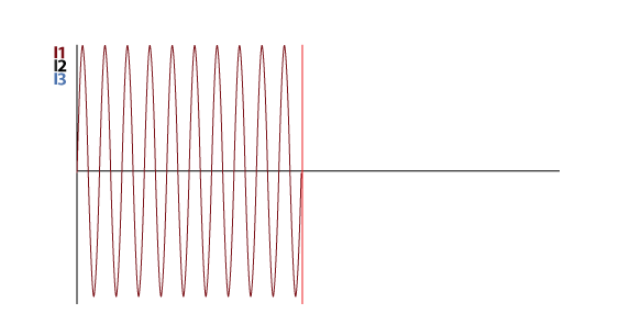
A fault is suddenly applied to the system and the sine wave suddenly becomes asymmetrical (the positive and negative peaks are NOT equidistant from zero), and then returns to normal (symmetrical) after a few cycles.
The asymmetrical response to the fault is called DC Offset and it is a naturally occurring phenomenon of the electrical system. Design engineers need to compensate for DC Offset when creating engineering studies, high-voltage equipment must be able to interrupt the larger current created by DC offset, and electrical personnel who look at oscillograph reports can use DC Offset to recognize real faults. If this is such a normal part of the electrical system, why is it so hard to find a good description of DC offset?
Here are some other descriptions from various textbooks:
“The actual magnitude of the DC current is dependent on the point of the voltage wave where the fault occurs and the circuit angle (X/R).”
“A symmetrical fault is a balanced fault with the sinusoidal waves being equal about their axes, and represents a steady-state condition.
An asymmetrical fault displays a DC offset, transient in nature and decaying to the steady state of a symmetrical fault after a period of time…”
“Direct current offset…occurs as a result of two natural laws:
- Current cannot change instantaneously in an inductance and
- Current must lag the applied voltage by the natural power-factor…”
You can get a more detailed description in Protective Relaying: Principles and Applications, second edition, by J. Lewis Blackburn, but you have to have a very good understanding of power systems to understand all of the nuances in the description.
“When a current change occurs in the primary ac system, one or more of the three-phase currents will have some dc offset…from the necessity to satisfy two conflicting requirements….
- In a highly inductive network…, the current wave must be near maximum when the voltage wave is near zero; and
- The actual current at the time of change is determined by prior network conditions…”
An excellent description is also provided in Protective Relaying for Power Generation Systems by Donald Reimart:
“At first glance, the occurrence of a DC current in an AC power system seems illogical. To understand its existence, let us look at a few electrical rules learned in EE 101. First, in an inductive circuit, the current lags the voltage by 90°. If a fault occurs when the voltage is zero, the current must be at the positive or negative maximum value. Secondly, the generator is a large inductor. The current in an inductor cannot change instantaneously.”
Let’s break this explanation down into its components and look at a few different scenarios.
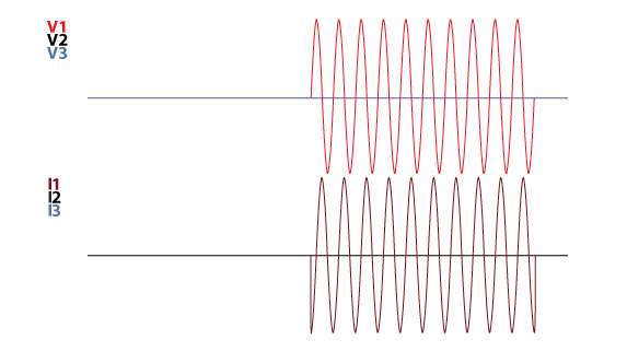
If you set your test-set to start with zero volts and zero amps and then apply a resistive condition (voltage and current in-phase), the test-set would produce symmetrical waveforms that start at zero and are in-phase as shown in the following image:
If we apply a purely inductive condition (current lags voltage by 90°), the output looks something like this:
Did you notice that the test-set cheated? It needed to maintain the pure inductive relationship of zero volts equals maximum current, so it started the voltage at the first peak while the current started at the zero-crossing. It could also cheat the other way by starting the voltage at the zero-crossing while the current starts at the peak:
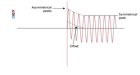
The current can’t make an instantaneous jump in the real power system like a test-set can, but it still needs to maintain those two conflicting rules of electricity at the same time. Whenever the electrical system experiences a large jump in current, a DC signal appears to create asymmetrical waveforms so that both of our electrical rules can be true at the same time as shown in this image:
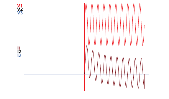
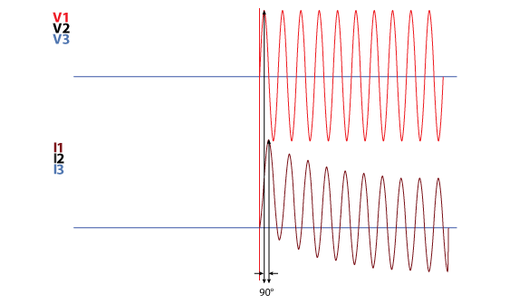
Do you remember the first rule? “…the current lags the voltage by 90°…” If we draw a vertical line through the positive peaks of the voltage and current in a cycle from the example, we can see that the current is lagging the voltage by 90°. Therefore, our example with DC Offset satisfies the first rule.
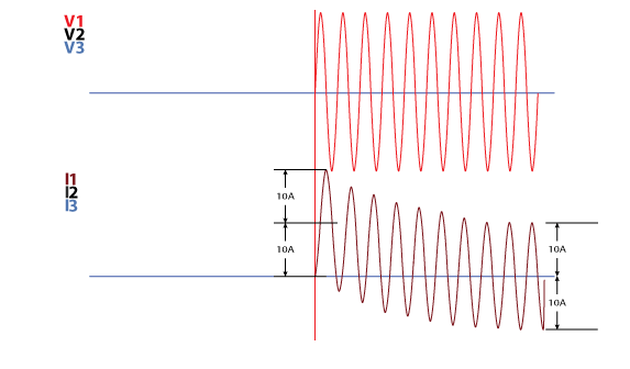
Let’s look at the second rule. “If a fault occurs when the voltage is zero, the current must be at the positive or negative maximum value”. The current waveform has a zero-crossing AND is at its negative peak, so we can see that the second rule is satisfied as well.
DC Offset is necessary to maintain the basic laws of electricity at the initial moment when the current in the system makes a sudden change, like what happens during a fault. However, the generators will be able to react to the new system conditions, and the DC Offset will decrease over a few cycles until the waveform is back to its normal symmetrical condition.
The size and duration of DC Offset depends on:
- The ratio of reactance and resistance (X/R) of the circuit during a fault. This includes the generator coils, and the equipment connecting the generator to the fault. The X/R ratio at the generator is typically very high because the generator is almost a pure inductor, which means that the DC Offset will be greater when the fault is closer to the generator. The system does not consist of pure inductors, so the resistance in the X/R ratio grows as the distance between the fault and the generator grows, which means the time constant will be larger. Also, the offset will be less extreme as a result of an increase in source impedance.
- The voltage magnitude at the exact moment of the fault. A fault at zero degrees on the A-Phase voltage means that there is zero voltage when the fault is applied to the system. When the voltage is zero in an inductive circuit, the current must be maximum. Therefore the maximum DC offset occurs when the voltage is zero. Remember that when the A-Phase voltage is zero, the other two phases will not be at zero, so different phases will react to the same fault differently.
- The ability of the generator(s) to react to the fault and time necessary to stabilize the system.
Faults rarely occur at exactly zero degrees as shown in our previous examples. Faults can occur at any point on a voltage waveform and different people may use different terms when describing this moment. For example:
- Manta Test Systems refer to it as the Fault Incidence Angle (FIA)
- Omicron uses the term Fault Inception Mode/Angle
The amount of time that it takes to go from fault inception with DC offset to to steady-state symmetrical waveforms can also have different descriptions:
- Doble uses the “Time Constant L/R” setting
- Manta Test Systems uses the setting “System Time Constant”
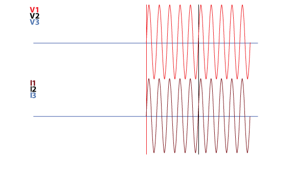
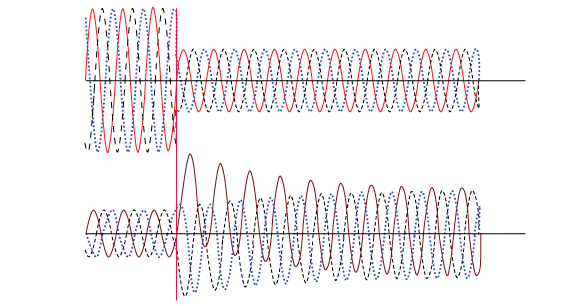
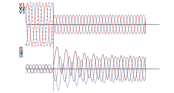
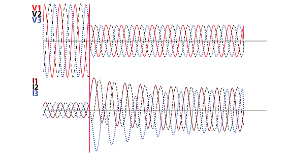
The next images show the same fault with different fault incidence, or fault inception, angles.
Fault Incidence at 0° with a 50ms Time Constant
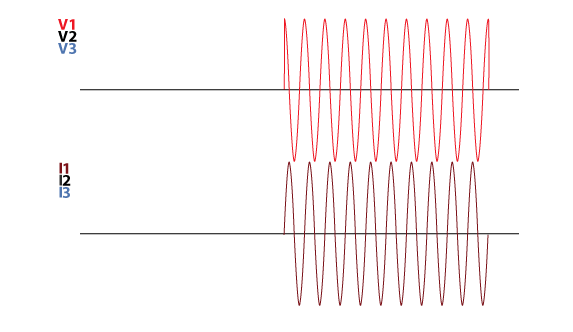
Fault Incidence at 30° with a 50ms Time Constant
Fault Inception at 60° with a 50ms Time Constant
Fault Inception at 90° with a 50ms Time Constant
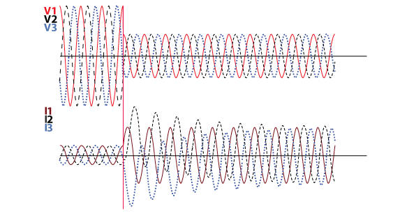
Did you notice that the three voltages experience the initial fault at different points on their waveforms? And that the DC Offset introduced to each current waveform is different even though the fault happens in the same moment for all phases? Do you see that the individual phases do not respond to the different angles in the same way?
DC Offset is something that all relay testers should understand because it is a normal part of the electrical system. You can use this information to properly interpret oscilligraph reports, or tweak your test plans so that they will be more realistic and therefore, more reliable.
I hope that I was able to properly answer this question and help you understand this ever-present, but seldom understood, aspect of the electrical system. If you want to get a different perspective that is much more comprehensive, you can click here to download an excellent white paper titled “Fault Calculations for Circuit Breakers that is courtesy of Erik C. Baker, P.E., Affiliated Engineers, Inc..
Please share this post with the buttons below to help Google realize that we should have a high rank in their search results.
Do you have a nagging electrical question that has never been answered to your satisfaction? Use the “Ask Chris” form and it could become a post here.
And if you click below and subscribe, we’ll send you a free quick-reference PDF cheat sheet to go along with this guide that you can take with you:
Discover more from Valence Electrical Training Services
Subscribe to get the latest posts sent to your email.
Did you like this post?
You can share it with these links:
Read More Articles:
The Relay Testing Handbook Updates
Hey, Chris,
This article is very helpful. I had a question from a customer where they got RAW event reports out of an SEL and didn’t know why all those DC offsets were showing up. I referred him to your article. One question: in point #1 above, you said “The system does not consist of pure inductors, so the resistance in the X/R ratio grows as the distance between the fault and the generator grows, which mean less DC Offset will be required to meet all of the laws of electricity.”
I wonder if it would be more precise to say: “The system does not consist of pure inductors, so the resistance in the X/R ratio grows as the distance between the fault and the generator grows, which means the time constant will be larger. Also, the offset will be less extreme as a result of an increase in source impedance.”
Thanks for the excellent suggestion, Walt. I made the suggested change in the post.
Chris
i has an DR from site, where the bus fault level is 40kA but the actual bus fault current was more than 106kA, and the waveform appears completely distorted. what i am refering is from generating station. So huch higher fault current is due to higher X/R ?
It’s hard to say without a lot more detail. If the shape looks like the ones in this post and you are referring to peak values, then yes.
How about predominantly capacitive circuits near cap banks – do we expect the DC offset in Voltage Trace at current zero crossings? I believe I recall seeing something like that on fault records – but I did not understand it so I had to let it go. Thank you for great explanation finally it makes sense after staring at it in fault records for a decade…
Additionally faults that occur on waveforms that are not at zero crossing induce traveling waves (step surges) that show up as hi frequency oscillations on current and voltage traces. They show up if the fault record is sampled at high enough frequency so that may partly explain distorted waveform. Another reason for distorted waveform might have been severe CT core saturation due to DC offset (in an attempted answer to kathik’s question above).
This article has helped me to understand symmetrical waveform and deepen my knowledge of fault analysis using waveform.
Chris excellent explanation
Thanks!
Very nice explanation. Your input and explanation is a super asset to power system industry
I have been reading about the DC offset but without much insight. The article really provided interesting explanation. The graph may be expanded horizontally for seeing clearly the relationship between voltage and current. Also a background grid might help. An excellent article.
Thanks for the kind words and the suggestion, unfortunately my Adobe Indesign skills aren’t good enough to get everything right enough for close inspection.
Excellent description I must say…
Hey Chris, how does the value 2.55 times peak value for DC offset being derived?
I parroted it from a textbook.
Great explanation Cris!! Now I understand, why generators have high X/R ratio (in the range of 90 to 100). Could you please, explain the theory of Sequence Components, and deriving sequence diagrams for various equipment (Generator, Transformer, Line etc.). if already done, please provide the link.
We wrote about Sequence Components in The Relay Testing Handbook: Principles and Practice. Relay testers only need to understand the basic patterns, not the rest.
Thanks for the excellent insight. Is there any calculation to correlate dc time constant (or X/R) with zero crossing and estimating current peak after a certain period of time (depending on circuit breaker – 3 cycle, 5 cycle etc.)?
You would have to model the entire system and perform a fault study. The coordination and arc flash study for wherever you are gives you that information.
Very well explained post! Thanks Chris. Now I am going to dig into your website.
Thank you! I’m glad it was of use to you.
Excellent
Very useful information presented clearly and in a simpler way to understand. Well done.
Hi Chris,
Thank you for all the content that you post on your website.
The DC offset can be caused in power system by the circuit breaker operation.
As you know, voltage and current are not in phase and a circuit breaker will always try to break a fault when the current pass the zero crossing.
by doing that, it will cause the voltage to “jump” and create this DC offset.
Fault recorder can be a good solution to observe and analyse this phenomena in detail.
Hey Chris, I just got a question. Most RCD tests are using A.C. supply. However, is the result will be affect if the DC component exists in the circuit? If yes, under what condition will DC component exist in the AC circuit?
Thanks for your question. Unfortunately, I don’t understand what an RCD test is, what tests don’t use a AV supply, and what you mean about DC components. A specific example might help.
Thanks a lot for the valuable information and brilliant explanation. I would like to ask an important question and I haven’t found an adequate answer yet. The DC offset explained above is contaminated in the grid current only, but with synchronization techniques proposed recently implemented on the grid voltages and I have tested the DC offset contaminated in the grid voltages during the fault and it was negligible value. So, why the approaches implemented based on the grid voltages instead of currents if the DC offset affects the currents only? Is there any valuable information against the DC offset in the grid voltages?
The amount of DC offset depends on the X/R ratio between generator and system change. You will see more DC offset when close to a generator and it will decrease as you get further from generation. Your system modelling software can predict the X/R ratio wherever you are in the grid.
How is DC Offset voltage created on AC power supplies by non linear loads, such as switched mode power supplies from IT equipment.
I have seen a case where such DC Offset voltage existed between the neutral to ground, phase to neutral, and phase to phase voltages of a 364V/208V, 3-phase, 4-wire, 50Hz system. The DC Offset was in the range 28vdc to 50vdc.
We are talking about the power system and high voltages in this article. DC offset happens to current, not voltage.
Very well explained