Alternating-Current Systems from Silent Sentinels 1924
Silent Sentinels 1924 Excerpt #3
This excerpt from the 1924 version of Silent Sentinels discusses how electrical engineers understood how alternating-current systems (AC) operated in 1924. This is the 3rd in the series. Follow these links to learn more about this series and the 1924 version of Silent Sentinels. We also cover this subject in The Relay Testing Handbook: Principles and Practice.
1 – General Theories of Line Troubles
Alternating-current systems suffer from more severe short circuits than do direct-current systems, primarily because of their better inherent regulation and often because of the greater power concentration. Modern polyphase systems have become so large and complicated that they present many difficult problems, due to the various unbalanced faults which can occur.
Alternating-current transmission systems may be divided into two general classes:
- First, those having the neutral insulated from ground.
- Second, those having the neutral connected to ground metallically.
The second classification may be further sub-divided into four groups, known respectively as solidly-grounded neutral systems, low-resistance-grounded-neutral systems, medium-resistance-grounded-neutral systems, and high-resistance-grounded-neutral systems. The solidly grounded-neutral system is one having its neutral connected metallically to ground without any limiting resistance in the circuit.
The terms low-resistance, medium-resistance and high-resistance refer to the relative values of the limiting resistance inserted in the neutral connection between the neutral point of the system and ground, and are dependent on the neutral voltage of the system under consideration. As a general rule a system may be considered as low-resistance-grounded neutral if the grounding resistor is of such a value as to produce in any circuit, for a fault to ground, a current which, under minimum generating capacity conditions, is at least four times the line relay current setting.
A medium-resistance-grounded neutral system has a grounding resistor of such a value as to limit the current for a fault to ground to less than four times the current setting for the line relays of that circuit. This “fault” current will still, however, be greater than the maximum load current over the feeder, even under abnormal operating conditions.
A high-resistance-grounded-neutral system has its grounding resistor of such a value that the current for a fault to ground is on the order of full-load current of the grounding transformer bank, or less. Protection for faults from wires-to-ground may or may not be possible, depending upon certain local conditions which will be discussed under “Methods of Clearing Ground Faults.”
Solidly-Grounded Systems—Systems having their neutrals solidly grounded are subject to short circuits between one wire and ground, whenever that wire becomes accidentally grounded. They can also suffer from short circuits between only two wires of the system, as well as between two wires and ground. In addition to these unbalanced short circuits, such a system can suffer from a balanced three-phase short circuit. In considering a system which has its neutral grounded, it is customary to assume that the ground resistance between the neutral and the fault is comparatively low, so that it does not decrease the value of the short-circuit current by any great amount. However, in some localities the ground resistance may be high, but such conditions are not of common occurrence. In calculating the quantity of ground current likely to flow, it is important to bear in mind that the impedance of the circuit is high, because of the great separation between the line wire and the path through the ground.
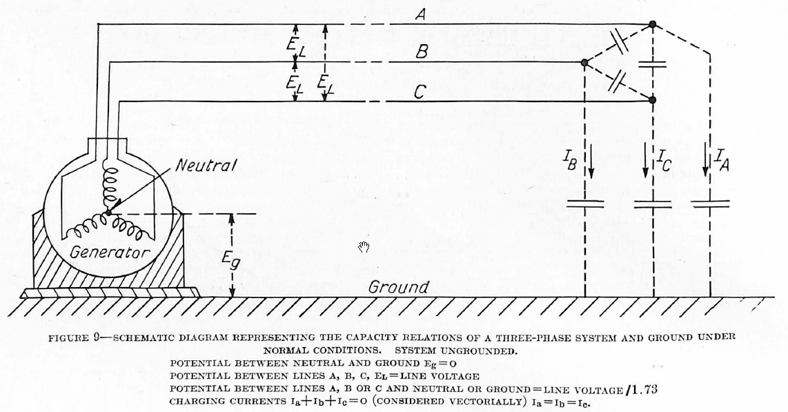
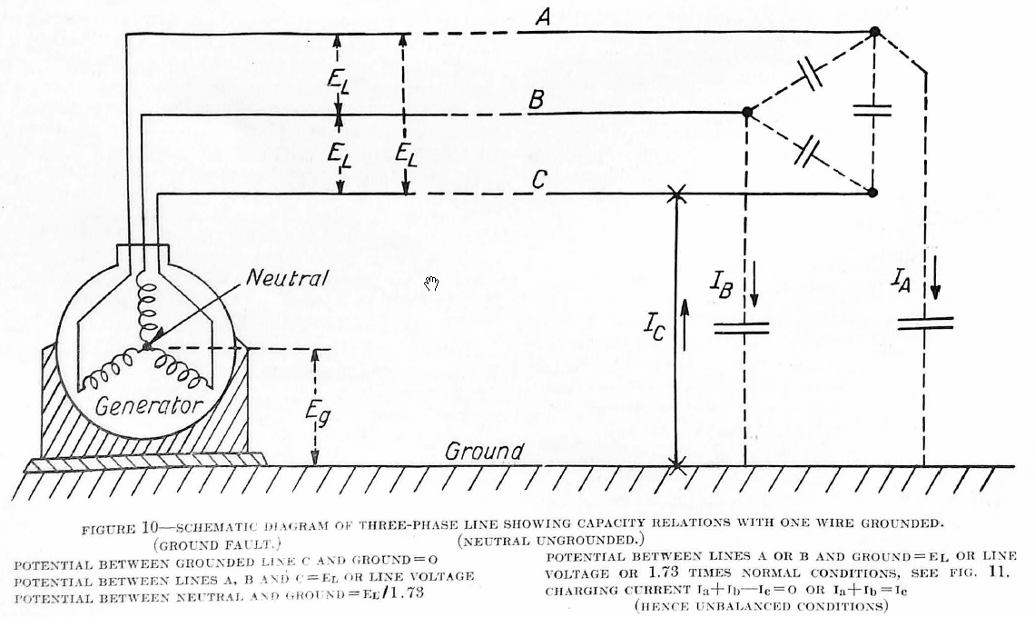
Ungrounded Systems—On systems having an isolated neutral, the three-wire short circuit and two-wire short circuit are the same as on grounded systems, but an accidental ground does not produce a short circuit as it does in the solidly-grounded system. If the system is small, an accidental ground will make little disturbance, or at least it will not cause any abnormal value of current to flow, but if the system is large in extent, so that the electrostatic capacity between conductors and ground is high, a noticeable charging current will flow into the fault. On a large system there is always a charging current flowing in the conductors, but such a charging current is normally balanced and is distributed throughout the network. When an accidental ground occurs on one wire, the potential between each of the other two conductors and ground throughout the system is increased beyond its normal value by the factor 1.73, and these wires, therefore, require a greater charging current than that which they normally carry. As shown in Figure 10, each of these wires represents a plate of a condenser, the ground being the other plate, and the wire leading to the fault represents the connection between the source of potential and the ground plate. Therefore, this grounded wire must carry all the charging current for the two condensers. The value of this current is difficult to calculate accurately, but an approximate value can be very easily obtained, and it is about twice the normal charging current of the system. The normal charging current can be calculated from tables which take into account the size and spacing of the conductors and the frequency of the circuit.
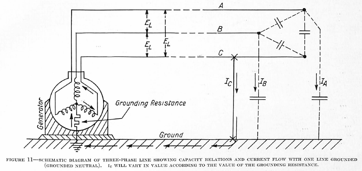
Reason for Grounding Through Resistance—If an ungrounded system is small, with a consequently small charging current, it is possible to operate the system when one of the conductors is accidentally grounded so that the necessity for cutting out the disabled section is not urgent. Furthermore, most grounds are usually of a temporary nature, such as a flash-over on an insulator, and they will clear themselves without damage. If the system is large these disturbances will become more frequent and the charging current will increase, due to the greater electrostatic capacity of the system, to such a value that an arc over the insulator will not break, but will continue until serious damage has been done and until the line probably is burnt down. Therefore, on large systems it is necessary to provide some means of cutting out a disabled section and this, usually, requires some method of grounding the neutral. Grounding is also necessary in order to relieve strains on insulators because as has been shown, when one line is accidentally grounded in an ungrounded system, the voltage between the other two lines and the ground is increased 1.73 times. The solidly-grounded neutral has been considered, and it was shown that an accidental ground on a conductor results in a short circuit. This causes considerable disturbance which is frequently so severe that some of the load, particularly synchronous motors, will be forced to drop off the system before the fault can be cleared. This disadvantage may be overcome by inserting sufficient resistance in the neutral connection to limit the current to a small value so that an accidental ground will not seriously disturb the load. Sometimes this resistance is so low that the ground current approaches a short circuit in magnitude and can therefore be handled by ordinary relays intended for short-circuit protection, but it is becoming a common practice to use a resistance of such magnitude that the ground current is kept below the full-load value of the current in any of the feeders. This is particularly useful in cable systems because cable faults usually start between one conductor and the grounded lead sheath, and as the ground current is held to a small value, it is possible, by means of suitable relays, to disconnect the faulty cable before the trouble has developed into a short circuit with a consequent interruption to the nearby load.
Nature of Open-Wire Short Circuits—The nature of a short circuit, and its effect upon relay operation have been determined both by experiment and years of experience. On overhead lines short circuits are usually arcs and the resistance across them is small and of a fairly stable value. Short circuits of this nature sometimes cause extensive trouble wherever there are several transmission lines on the same structure due to the blowing of the arc from one circuit to the adjacent ones. Flashovers caused by lightning are a particular annoyance because the lightning usually strikes on the windward side of the structure (the lightning coming with the storm) and the wind then may blow the arc across all the other circuits. For this reason, it is advantageous, if possible, to disconnect the first line in trouble before the arc has had time to involve the neighboring lines, but this is always difficult and usually impossible to accomplish.
Several cases are known where trouble has communicated itself in this manner to several parallel circuits each of which was equipped with practically instantaneous relays and yet the circuit-breakers could not open fast enough to clear one line before the arc had blown across to the other lines. In checking some of these faults the weather bureau records were consulted and it was found that the average wind velocity at that station was about four miles per hour which corresponds to approximately six feet per second. When it is considered that an arc has no inertia, it is easy to see why trouble on one circuit will involve the neighboring circuit even on a quiet day.
It sometimes happens that in testing lines after an extensive interruption, the switchboard operator closes-in the good lines first and then closes-in the bad line, thus starting trouble which involves all the lines and trips them out again. Therefore, in testing circuits, it is good policy to vary the sequence of closing the breakers after one sequence of operation has failed to hold.
On systems having a large connected generating capacity the length to which an arc can be drawn out by the wind is almost unbelievable. Arcs more than 20 feet long within a station have been seen, and authentic cases are recorded of arcs having a length of 200 feet or more on high voltage lines. These long arcs usually occur on lines of 66,000 volts or above, but where towers are used to support the structure it is surprising how seldom they jump from one circuit to another. This is probably because the grounded steel tower acts as a shield between the circuits at the point where the trouble starts; namely, at the insulators.
Nature of Trouble in Cables—Because trouble in cables usually occurs at the joint in manholes where there is danger of injuring adjacent cables it is essential that the defective section be disconnected within a reasonable time. Tests have been made on a 11,000-volt system which prove that the voltage across the arc between the two conductors amounts to two or three per cent. of normal voltage, the value being practically independent of the current. This is easily explained if we assume that the resistance of the arc decreases as the current through it is increased. These tests were made by sawing off the cable and allowing the arc to form between the conductors at its end. It is not only possible, but also probable, that when the arc is confined in the cable its resistance will increase as the pressure increases due to the generated gases, and this, naturally, will increase the voltage across the arc. This voltage will insure the correct operation of directional relays even when a fault occurs close to the switching station.
Most faults start as a ground between one conductor and the lead sheath, usually due to the entrance of moisture into the cable. By means of a suitable relay installation, it is often possible to disconnect any of these faulty cables before the arc has involved the other two conductors. One operating company has found, by an analysis of the defective sections of the cable, that about 50 per cent. of the cable troubles are cleared without developing short circuits.
Power Factor of Short Circuits—It is the general impression that short circuits are of low power factor, but this is usually not so. It is true, of course, that the total reactance of the circuit involved in the short circuit is high compared to the resistance, but most of this reactance is in the apparatus, and is not usually of importance in relay work. We are interested usually in the power factor of the line itself during times of short circuit and this, of course, depends on the relative resistance and reactance of the line conductor and is, therefore, independent of its length. High voltage 60-cycle overhead transmission lines sometimes have a power factor of less than 50 per cent., but this is not the rule, and 25-cycle lines and all cable circuits have a much higher power factor. It should be remembered, however, that the power factor of a short circuit or ground fault may vary widely according to conditions, and this fact should always receive consideration when applying relays, especially those dependent for their operation upon both voltage and current.
Distortion of Phases—In faults involving all three wires of a three-phase system the only abnormal conditions which ordinarily will exist are the excess flow of current into the fault, and low voltage in its vicinity, but these present no difficulties in relay protection.
Any other fault which may occur, such as a two-wire short circuit, or a ground on one or two wires (3-wire, 3-phase system considered), will not only cause an abnormal current flow, but will also necessarily result in an unbalanced or distorted condition of phases, on account of the abnormal current flow being in only one or two of the three lines. This distortion is greatest in the vicinity of the fault, and gradually lessens as the distance from the fault increases.
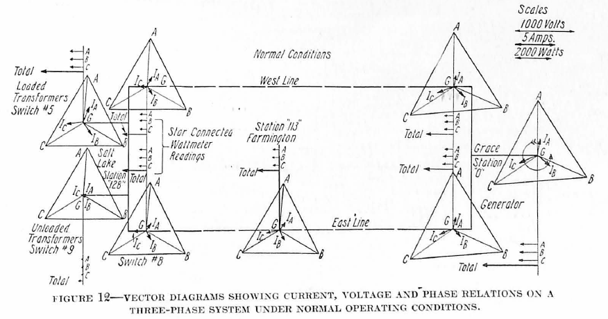
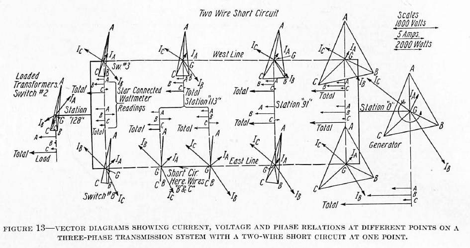
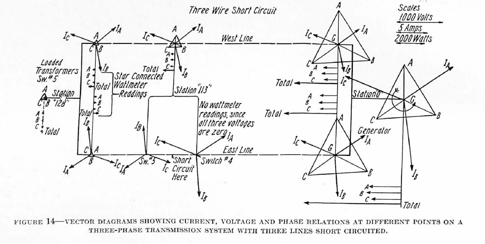
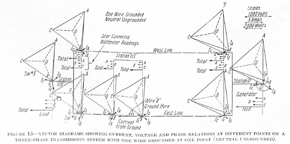
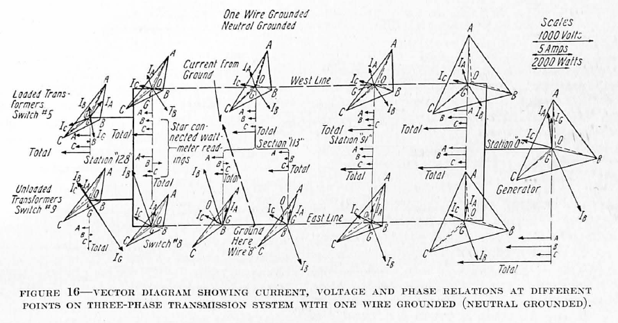
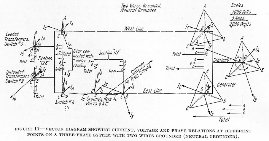
Exact conditions existing after a short circuit or ground has occurred are hard to determine because so many conditions and characteristics are present in every system which vary widely in different systems. Some few years ago Mr. G. H. Grey and Mr. L. N. Crichton made extensive tests respecting such conditions, using an artificial transmission line for the purpose. Figures 12, 13, 14, 15, 16 and 17 show some of the results of these tests plotted vectorially. The values plotted were taken from oscillograms and thus represent actual conditions existing after the fault occurred.
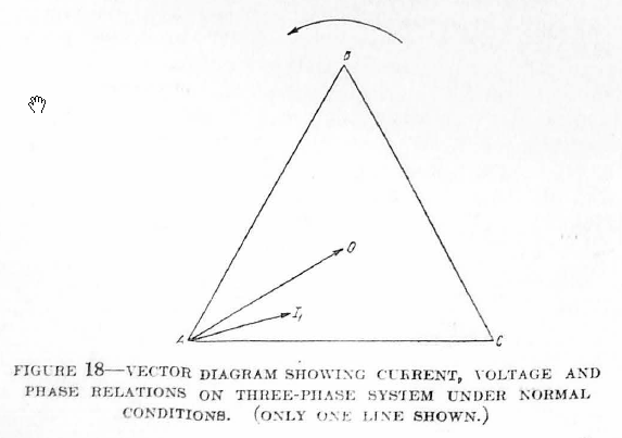
Effect of Phase Distortion on Relay Operation—Phase distortion has no effect on the operation of straight overcurrent relays. In the case of directional relays, however, where the correct operation of the relay is dependent on the operation of a wattmeter element, phase distortion must be considered. A true wattmeter will reverse if the angle between the current and the applied voltage becomes greater than 90 degrees. Therefore, the problem in the application of directional relays is to make the voltage and current phase relation such that the worst conditions of phase distortion will never cause the angle between the current and voltage to exceed 90 degrees.
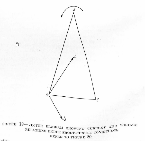
The vector diagrams, Figs. 18 and 19, show the conditions which may exist. In Fig. 18 the current and voltage vectors of only one phase are shown. A0 represents the voltage from A to neutral and I1 represents the current in leg A with a slightly lagging power factor. Fig. 19 shows a possible distortion of phases when a short circuit occurs from line A to C. A short circuit of unity power factor would mean a heavy current in phase with voltage AC, but due to the reactance of the circuit the current would probably lag considerably more and would take a direction as shown by the vector I2. AO, the voltage to neutral, changes its direction only slightly and, as is evident, the angle between AO and I2 may easily be greater than 90 degrees. Now, if a directional relay with a wattmeter winding has its voltage coil connected to AO and its current coil to phase A, it will tend to reverse as soon as the angle OAI exceeds 90 degrees. It will thus close its contacts and trip the circuit-breaker with current flowing in the normal direction (opposite to that for which the relay is supposed to trip).
Actual tests have shown that the angle OAI2 may be as great as 120 degrees with a short circuit between A and C. This will cause directional relays to close their contacts on normal direction of power flow when the directional contacts should be held positively open.
The most satisfactory solution of this problem is to connect the potential coil of the relay to a voltage which is 30 degrees behind the current at 100% power factor. Referring to Figs. 18 and 19, if the voltage were taken from phase A to C, then under short-circuit conditions, the angle CAI always would be less than 90 degrees and the directional relay contacts would never close on normal direction of power flow.
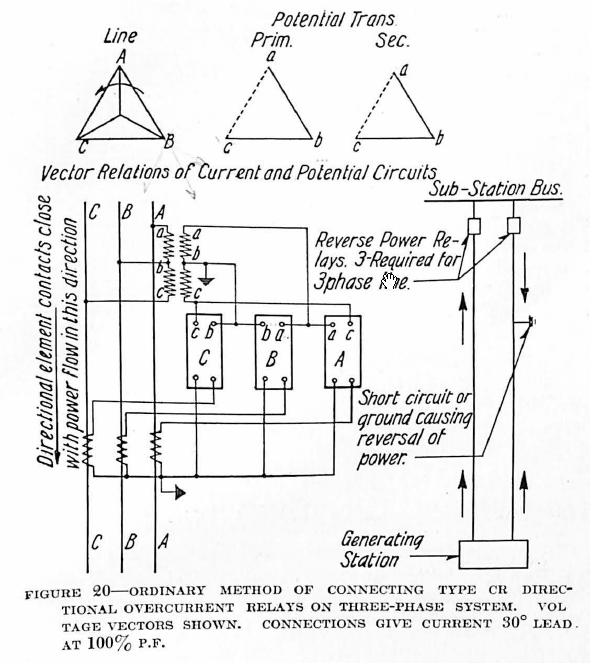
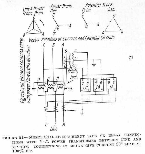
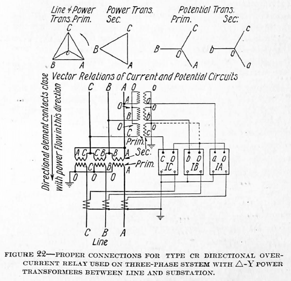
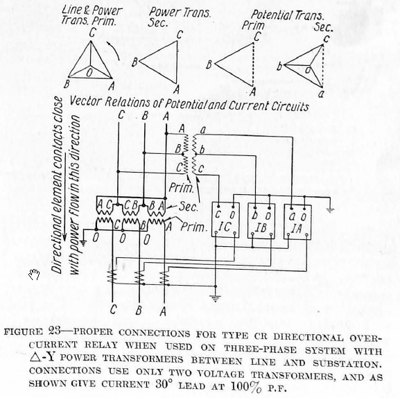
Phase Relations with Delta-Star Connected Transformers
Where directional relays are to be applied at substations having delta-star connected power transformers, it is often desirable to connect the voltage transformers on the low-voltage side while it is necessary to have the current transformers connected in the high voltage leads in order to get the true current flowing. Special care is necessary in such cases in order to secure the connections which will give the proper phase relations between the voltage and current for the relay. As already stated, in order to assure proper operation of the relay with the phase distortion accompanying a short circuit or ground, the relay current should lead the relay voltage by 30 degrees under normal conditions with 100% power factor on the system. Figs. 20, 21, 22, and 23 show the correct connections for such combinations to be used in applying type CR directional relays. The vectors show the relative phase relations for each step of transformation.
Discover more from Valence Electrical Training Services
Subscribe to get the latest posts sent to your email.
Did you like this post?
You can share it with these links:
Read More Articles:
Methods of Clearing Short Circuits from Silent Sentinels 1924