SEL Test Procedure Negative-Sequence Volt-Pol Directional Overcurrent Element
I am writing to enquire about 67N test procedures, specifically Schweitzer relays. The Page 94 of the Relay Testing Handbook #C2 : Practical Relay Testing (50/51/67/59/27/81/87/21) by Chris Werstiuk says “some relays, such as SEL models, do not have user defined characteristics and operate dynamically based on actual operating condictions” I would be grateful if someone could send me further details regarding about the best way to test this function ( 67N-directional overcurrent ) in Schweitzer relays related with settings Z2R, Z2F (Negative-Sequence Voltage-Polarized Directional Element for Ground Distance and Residual Ground Overcurrent Elements).
Best Regards
adolf2012
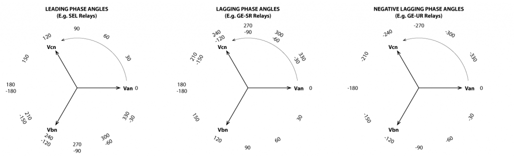
This is the figure mentioned in the comments for page 611 to help describe the Directional Overcurrent Element phase angles in an SEL relay.
Discover more from Valence Electrical Training Services
Subscribe to get the latest posts sent to your email.
Did you like this post?
You can share it with these links:
Read More Articles:
SEL-321 Out-of Step Protection Problem?
Hello,
As long as the settings are used for polarizing and are set correctly, the steps described in the the “C)Quick and Easy Directional Overcurrent Test Procedures” section of The Relay Testing Handbook 67 or overcurrent chapter will work.
Because you are applying an unbalanced voltage and an unbalanced current, you will automatically create negative sequence impedance (Z2)(as well as negative sequence voltage, current, zero sequence voltage, current, impedance, etc) that the relay will use for it’s polarizing element. If you want to guarantee operation, you could set the faulted phase voltage at 0 to create the maximum possible Z2. You could make calculations to determine the Z2, Z2 Angle, and unbalanced current magnitude and angle; but I never found it to be necessary. Remember that the relay might be looking at crazy polarizing values, but in the end, it is really just using the most reliable signal to determine if the fault is in the forward or reverse direction. If you create a realistic looking fault in the right direction, the relay should operate correctly using whatever polarizing signal it needs. If it doesn’t operate with a realistic looking fault, start asking the setting engineer some questions.
If the relay does not operate near the pickup. The engineer may have un-intentionally set a blinder. I once had an engineer set the polarizing impedance higher than realistically applied quantities and the test procedure did not work. The engineer was able to create a scenario that would operate the element, but when I pointed out that I was simulating a system fault and he was creating a test procedure to make the relay trip with unrealistic number, he took a longer look at the settings and then corrected the mistake that he had made.
Hope this helps.
what is meant by the -30 degree value SEL uses when testing the directional overcurrent. would it mean that to produce a fault angle of -60, ill input a current of -30 degrees.
read this in the tips at the end of directional overcurrent chapter
I believe that this is the quote you are referring to “Different relay manufacturers have different phasor references. Make sure you understand the manufacturer’s phasor references. For example, GE relay phasors use a lagging reference; SEL relays use a leading reference. 30º displayed on a GE relay is -30º on an SEL relay.”
This sentence is more for GE relay testing because the MTA is defined in settings, but that setting uses a lagging reference that may be confusing to someone who is used to SEL references, for example. If a GE relay setting is 30 degrees, a person may think that they should set their current to lead by 30 degrees, not realizing that all GE angles are lagging.
See page 611 or this figure for more details.

i also have the same question and i need answer