Introduction to Breaker Failure Schemes (50BF)
I presented a “Testing Breaker Failure Schemes” paper at the 36th Annual Hands-On Relay School in 2019. Here’s the first part of the paper that will give you a basic introduction to Breaker Failure Schemes:
1. Introduction
The power system is a delicate balance between load and generation. We usually think that brownouts and blackouts are only caused by faults on the system, but they can also occur when the load is greater than the available generation; or when there is more generation available than load. Protective relays detect faults and isolate them from the rest of system before they destabilize the entire grid and cause system-wide outages. History has shown that every extra moment a fault is energized can destabilize a larger part of the power grid. All transmission system protection is designed to minimize the fault time to protect the entire grid. Every cycle counts!
Any important node on the power system will have:
- An
isolating device (circuit breaker/circuit switcher) to energize and isolate a
section of the power system. - Instrument
transformers (CTs/PTs) to reduce the primary voltage and/or currents to
smaller, secondary values to minimize the size of protection equipment. - A
protective relay that measures the CT/PT secondaries and equipment status to
detect problems on the power system that should be isolated. - A
separate power supply for the protection and isolation equipment that operates
under all power system conditions.
Electrical Engineers are constantly asking themselves “What if?” questions, trying to make the power system more reliable and stable. A cost/benefit analysis is applied to each “What if?” question. More questions will be asked if the equipment is vital to power system stability, or expensive. Transmission circuit breakers have a lot of questions because they are vital to power system stability. Some of those questions and answers include:
- What
if the PT fuse(s) operate? Add Loss-of-Potential logic that blocks any element
that uses voltage in its calculations. - What
if the zone of protection is large enough to trip when an overload occurs? Add
a Load Encroachment, or Fault Current-detector, blocking element that helps the
relay tell the difference between faults and overloads. - What
if the fault is still on the circuit when you close the breaker? Add Switch-Onto-Fault
logic to trip the circuit breaker immediately instead of waiting for the normal
time delay. - What
if the circuit breaker trip circuit fails? Add a redundant trip circuit with a
unique power supply, inputs, and trip coil. - What
if the protective relay fails? Buy a different model relay with the same
functions and install it as secondary protection that detects faults and trips
the circuit breaker. - What
if the trip coil circuit opens? Add Trip Coil Detection circuitry to provide an
alarm if a problem with the trip coil circuit is detected. - What
if both primary and secondary protective relays fail? Add backup protection on
adjacent nodes with extended time delays that gives the circuit breaker plenty
of time to trip after its local relays detect a fault.
There are plenty more “What if?” questions left, but the circuit breaker is still a weak link after all the other contingencies are accounted for. Breaker fail protection answers the question: “What if the circuit breaker fails to open during a fault?”
The power system depends on transmission circuit breakers opening when the protection and control system sends an “open” command. However, any of these circuit breaker problems could prevent them from opening:
- The
trip coil can’t operate when there is low, or zero, DC trip voltage at the
circuit breaker. - The
trip coil(s) could be mechanically or electrically damaged and unable to
operate. - The
tripping latches could be out of alignment and unable to release. - The
trip mechanism could be out-of-alignment or damaged. - The
primary dielectric might not be able to quench the arc created when the
contacts open because it is contaminated, low, or missing. - The
primary contacts could be fused closed. - The
fault current could be higher than the circuit breaker’s opening ratings.
2. What Should Happen When a Fault is Detected
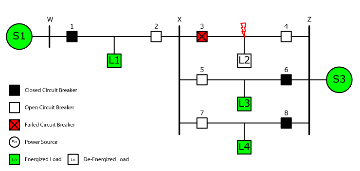
Before we dig into breaker failure schemes, let’s look at what is supposed to happen in a perfect world when a fault occurs between breakers 3 and 4, as shown in Figure 1.
Breakers 3 and 4 should both operate with no intentional time delay via their Line Distance (21), Zone 1 protection, or Line Differential (87L) protection, as shown in Figure 2. The ideal worst-case scenario happens when one relay on the line detects a Zone 1 fault and operates with no intentional time delay, then the other relay trips 15-25 cycles later after detecting a Zone 2 fault. Either way, the fault is isolated from the system with minimum disruption because L2 is the only load that is offline after the relays operate.
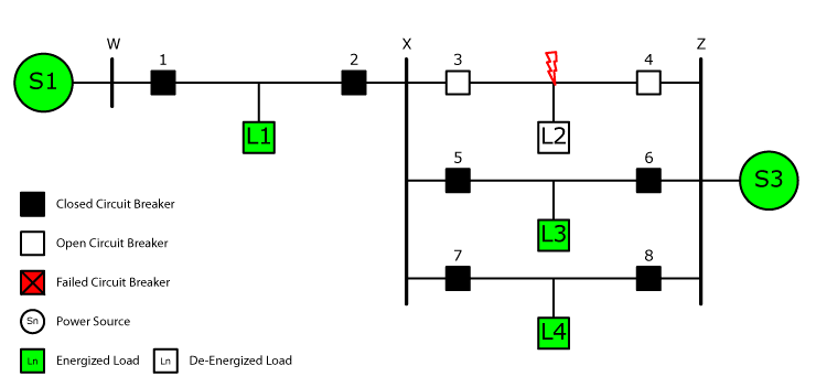
Figure 2 shows a time graph of the entire tripping process with both relays operating with no intentional time delay. The Total Fault Clearing Time in an ideal world equals the Local Protective Relay Time and the Breaker Interrupt Time. The Total Fault Clearing Time must be faster than the Critical Clearing Times, otherwise the rest of the grid may destabilize. You should notice that an element with “no intentional time delay” has a number of hidden time delays that occur in the real world. “Instantaneous” elements aren’t really instantaneous.
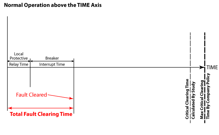
All of the information in Figure 2 can be summarized with the following descriptions:
- “TIME”
is the X-axis, which organizes all time delays involved that isolate a fault
from the power system. - “Local
Protective Relay Time” is the amount of time required by the relay to:- analyze
the input waveforms, - detect
the fault with calculations or pattern recognition, - ensure
the fault is on the system longer than the expected time delay, - send
a trip signal to its internal output contacts, and - close
its internal output contacts.
- analyze
- “Breaker
Interrupt Time” is the amount of time that the breaker takes to open and
isolate the fault when a trip signal is received under normal conditions. - “Fault
Cleared” indicates the moment that the fault has been successfully isolated
from the rest of the power system. - “Total
Fault Clearing Time” is the sum total of all time delays required to isolate
the fault from the rest of the power system. - “Critical
Clearing Time Calculated by Study” is the maximum amount of time that the fault
can stay on the system at that specific location before the system becomes
destabilized. The fault must be cleared within this time delay to prevent a
cascading system-wide failure. - “Critical
Clearing Time Calculated by Company Policy” is a safety margin that the utility
applies to all transmission lines to prevent system-wide cascading failures.
The fault should be cleared within this time delay.
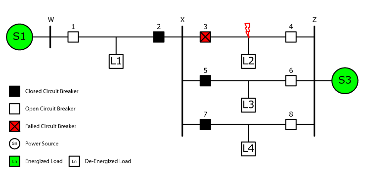
Figure 3 shows what happens when something goes wrong with the local protection and the remote Zone 2 backup protection in the relays connected to Breakers 1, 4, 6, and 8 operates instead. All four loads are now de-energized instead of just the load closest to the fault. The entire local power grid could also be in jeopardy because the delicate balance between generation and load could be tilted too far toward generation and cause problems everywhere.
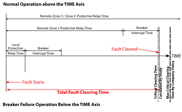
The time graph in Figure 4 shows what happens when the backup protection operates. Notice that the Total Fault Clearing Time is significantly longer than it was when the local relays tripped. The time delay could be longer than the Critical Clearing Times as well, which would destabilize the entire grid.
The situation changes with a Breaker Failure scheme, as shown in Figure 5. The Breaker Failure scheme received a trip signal when the relay tripped and waited for the circuit breaker to open. The circuit breaker did not open before the Breaker Failure Timer expired, so the Breaker Failure Scheme opened all of the circuit breakers directly connected to the failed circuit breaker to isolate the fault from the system. The three non-faulted loads were still energized after the fault was cleared, as they were when the local protection operated. The Breaker Failure Scheme prevented the catastrophe that occurred when the remote backup protection operated.
The time graph in Figure 6 shows the time delays associated with a Breaker Failure scheme.
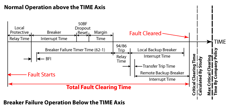
The new time delays in Figure 6 can be summarized with the following information:
- “BF
Dropout Reset” allows time for the Breaker Failure element (50BF) to disarm
itself after the circuit breaker opens to prevent mis-operations. - “Margin
Time” is an extra fudge factor to account for any problems that could slow the
breaker opening time. - “BFI”
is the time it takes the Breaker Failure Scheme to sense the trip signal sent
to the circuit breaker. - “Breaker
Failure Timer Time (62-1)” is the setting that determines how long the Breaker
Failure Scheme waits before sensing that the local breaker has failed before it
starts opening all of the circuit breakers required to isolate the failed
circuit breaker. - “94/86
Trip Relay Time” is the time it takes for any external relays to recognize the
Breaker Failure Trip, and send a trip signal to all the associated circuit
breakers that should trip to isolate the failed circuit breaker. - “Local/Remote
Breaker Interrupt Time” is the local breaker opening time to isolate the fault
when a trip signal is received under normal conditions. - “Transfer
Trip Time” is the time delay that occurs when a trip signal is sent through
communication equipment.
All faults should be cleared before the Critical Clearing Time. Breaker Failure Schemes allow the design engineer to ensure this happens locally without relying on backup protection.
3. Basic Breaker Failure Protection Schemes
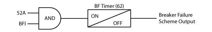
Basic Breaker Failure Schemes are pretty straightforward, as shown in Figure 6. The Breaker Failure Timer will start if the circuit breaker is closed AND the circuit breaker receives a trip signal. If the circuit breaker opens before the Breaker Failure Timer times out, the Breaker Failure protection will disarm itself. If the Breaker Failure Timer times out, a Breaker Failure Trip command will be sent to all the other circuit breakers connected to the failed circuit breaker.
Let’s look at each of the main Breaker Failure Scheme components in detail:
A) Breaker Status (52A)
The Breaker Failure (BF) Scheme needs to know whether the circuit breaker is open or closed before it can determine if the circuit breaker has failed to open. You might think that the design engineer can simply link the 52A contact from the circuit breaker into the scheme and call it a day, but remember that the BF scheme can trip multiple breakers at once. Breaker Failure schemes are relay testers’ greatest nemesis. There are many “famous” relay testers who have unintentionally tripped a BF scheme and can regale you with the chaos created when it happens.
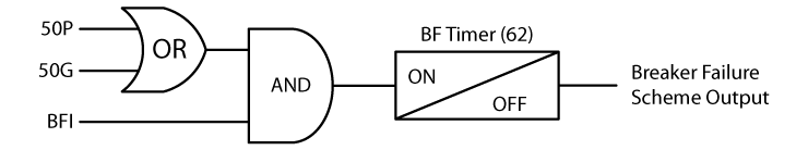
A good transmission engineer would never trust a small piece of plastic, like the 52A contact in a breaker, with something as important as a BF scheme. Therefore, BF schemes typically use phase and/or ground current-detectors to determine if the circuit breaker is open or closed. The breaker is considered closed if the measured current is greater than the current-detector setpoint, regardless of the 52A contact position. The circuit breaker is considered to be open if the current is less than the current-detector setpoint.
Most standards recommend setting the BF current-detectors higher than the normal load current to prevent mis-operations when a fault is not present on the system. A high current-detector setting means that the BF scheme will not open multiple breakers when an accidental Breaker Fail Initiate signal is sent under normal operating conditions, or maintenance testing. However, most current-detector settings I’ve seen in the field are set to the minimum possible settings, which means they are more sensitive, but less secure.
Most generator Breaker Fail schemes don’t use current-detectors. These schemes use the circuit breaker’s 52b status contact because a generator’s steady state contribution to a fault may be less than the recommended fault detector settings. In fact, circuit breaker (CB) contacts may be used whenever the expected current during a BF condition is less than the recommended fault detector setting. This makes the BF scheme less secure, as many people who have shut down an entire generating plant after racking out a generator breaker during maintenance testing can attest.
The generating plant shut down because the 52b contact opened when the CB was racked-out, which caused a BF Trip. From the relay’s perspective:
- The circuit breaker closed because the 52b
opened. - The undervoltage protection turned on because
the circuit breaker closed. - The undervoltage picked up because the generator
voltage was lower than its setpoint. (Remember that the generator is offline
and stopped for maintenance.) - The undervoltage timer expired and sent a trip
signal to the CB. - The Breaker Fail Timer started.
- The BF protection operated the Breaker Fail
Lockout Relay because the CB remained closed.
All the CBs connected to the “failed” CB opened and isolated the generating station from the rest of the system, and then heads started rolling.
This scenario is exactly why design engineers require current-detectors to determine whether the circuit breaker is open or closed, as shown in Figure 8.
B) Breaker Fail Initiate (BFI)
Any relay, or element inside a relay, that trips the circuit breaker should also send an identical Breaker Fail Initiate signal. Breaker Failure schemes with individual BF relays usually have a Breaker Failure Initiate circuit connected to the BF relay’s input(s) that are energized when a trip is sent to the circuit breaker. Manual open commands found in trip circuits are usually not included.
Relays with internal Breaker Failure elements usually have a BFI logic setting that includes every element set to trip the circuit breaker inside the relay. Other relays nearby that also trip the breaker will have a BFI output contact connected to an input in the relay. The BFI setting should also include the inputs from the other relays that trip the CB.
The BFI input should include any protection that should trip the circuit breaker.
C) Breaker Failure Timer
The Breaker Failure Scheme opens several circuit breakers and could cause havoc on the power system if it operates incorrectly. Therefore, the Breaker Failure Timer (62BFTD) delay should be longer than:
- the normal circuit breaker opening time, and
- the time necessary for any arcs to be quenched
after the circuit breaker opens, and - the BF element to detect that the CB is open and
disarm itself, and - a margin of time to account for unexpected
circumstances to give the CB plenty of time to operate before all the other
circuit breakers are tripped by the BF Scheme.
A typical BFT delay is between 15 and 25 cycles.
Discover more from Valence Electrical Training Services
Subscribe to get the latest posts sent to your email.
Did you like this post?
You can share it with these links:
Read More Articles:
How to Test Breaker Failure Schemes
I am very much happy and satisfied by these complete explanations on the topics of Relay functioning. Thank You very much
Thanks Chris, it is a neat and clear explanation on 50BF.. found it useful!