How to Test Protective Relays Correctly
Why I Wrote This Post
I was writing the next impedance relay testing post when I realized that a large part of it was going to be about the “right” way to test relays. I’ll just end up writing it over and over again in every post because these principles apply to all relays, so I figured that I should just write it down once to get it out of my system… and then link to it in all future posts.Background
I didn’t start my career as a relay tester. I started in a full-service, high-voltage testing company. My first job was running the ductor leads for a switchgear contact resistance test. I was very lucky because the company I worked for didn’t just teach the right button sequence to get a successful test; they wanted me to understand the principles behind contact resistance before we looked at the test-set controls, including:- Why I was performing the test.
- What the test was measuring.
- How the test-set was measuring it.
- How to connect my leads to get accurate results.
- What a good test result looks like.
- How to troubleshoot problems.
- make the right connections,
- run the test manually,
- understand what the results meant, and
- make sure they were correct.
How Should You Test Protective Relays Treatise
Electro-mechanical Relay Testing
Electro-mechanical relays had multiple failure points that could affect the relay pickup and timing characteristics. In fact, you can make one characteristic pass by changing another characteristic. For example, one of my students found the relay timing out of calibration. He temporarily forgot how to adjust the time delay and started adjusting the pickup characteristic instead. He managed to get all the timing tests to pass, but the student who checked the relay after him found that the pickup was nowhere near the calibration tolerances. The acceptance, commissioning, maintenance, and troubleshooting tests in electro-mechanical relays were all identical because the failure points in the relay didn’t change. You could calibrate and clean a relay to perfection today, and the electromagnetic and mechanical nature of the relay would cause the pickup, timing, and contact characteristics to change over time.Digital Relay Failure Points
Those electromechanical relay problems are almost impossible with digital relays. The functions either work, or they don’t. There is no reason to find the exact pickup points in a digital relay because there would be nothing to tweak to bring it into tolerance. The real failure points of digital relays are:- Analog/digital converters
- Power supplies
- Electronic components
- Digital inputs
- Digital outputs
- Relay algorithms
- Relay settings
- Relay setting engineers misunderstand how the relay functions.
- Relay setting engineers make a typo, or copy and paste error, when creating the settings.
- Relay testers convert incompatible setting files in the field.
- Relay testers incorrectly upload the relay settings.
- Relay setting engineers base their calculations on incorrect information.
A Relay Testing Analogy
Let’s simplify this by replacing the relay with a bank machine, or ATM, that distributes three kinds of bills ($5, $10, $20) stored in three separate hoppers. A smart and simple way of testing this bank machine is to install it, make sure it powers up, load it full of money using the standard procedure, and then walk through the withdrawal process as if you were a customer. If you ask for five dollars, you should get five dollars. Repeat the process for some basic combinations and head home after a couple of minutes.
The procedure I just described is called dynamic, or system, testing in the relay testing world. If I have a relay that is supposed to protect something, I will:
A smart and simple way of testing this bank machine is to install it, make sure it powers up, load it full of money using the standard procedure, and then walk through the withdrawal process as if you were a customer. If you ask for five dollars, you should get five dollars. Repeat the process for some basic combinations and head home after a couple of minutes.
The procedure I just described is called dynamic, or system, testing in the relay testing world. If I have a relay that is supposed to protect something, I will:
- find out which conditions should make the relay operate, and then
- create some realistic scenarios that are just within the relay’s operating tolerances, and then
- create some realistic scenarios that are just outside the relay’s operating tolerance, and then
- run the tests to make sure the relay operates when the test is within the tolerance and doesn’t operate when the test is outside the tolerance.
- Disconnect the keypad and replace it with a connection from the test-set that will virtually press buttons. (This would be similar to connecting your test-set voltage and current channels to the back of the relay the way the relay manufacturer shows the connections instead of looking at the drawing and trying to replace the CTs and PTs with test-set channels, using the site’s three-line drawings.)
- Disconnect the hopper that dispenses the bills and replace it with the test-set digital input feedback inputs. (This would be the same as mapping spare inputs for your relay testing.)
- Download the program from the machine, analyze the program, and create simple commands that will simulate the keypad presses required to get hopper #1 to operate.
- Repeat for hopper #2 and hopper #3.
- Run the three tests and make sure the correct hopper operates for each simulation.
- Disconnect the test-set from the ATM and reconnect the keypad and hoppers.
- Print your report.
 Which one is the right style for the ATM? Did you program the correct style when you built your test plan? You could go down a rabbit hole of research to press the correct virtual button with your automated test, but these questions are unnecessary when performing a dynamic test. If the right amount of money comes out when I pretend to be a customer with the ATM test (or the correct responses occur when I simulate a fault on either side of a relay pickup), I don’t need to learn the machine language responsible to prove that function is correct.
You can get passes on your test sheets in the relay testing world by looking at the relay terminals for your test-set channels, but the relay may never operate if the CTs or PTs are incorrectly connected to the relay. You can get passes on your test sheets AND find out if the CTs and PTs are connected to the relay correctly by connecting your test-set to the relay, using the site drawings. ALWAYS simulate real-world conditions when you can!
Downloading the program (relay settings), figuring out the ATM programming style (relay element names and references), and reviewing the ATM logic (relay logic) is something that an experienced tester or engineer can do after years of experience, but is it necessary to test the ATM (relay)? You can reverse engineer all of the settings to create a test plan, but you’ll only prove that the machine will do exactly what it is programmed to do, not that it is appropriate for the application. Garbage in usually equals garbage out.
For example, what happens to the numbering of the hoppers if we looked at the back of the ATM machine?
Which one is the right style for the ATM? Did you program the correct style when you built your test plan? You could go down a rabbit hole of research to press the correct virtual button with your automated test, but these questions are unnecessary when performing a dynamic test. If the right amount of money comes out when I pretend to be a customer with the ATM test (or the correct responses occur when I simulate a fault on either side of a relay pickup), I don’t need to learn the machine language responsible to prove that function is correct.
You can get passes on your test sheets in the relay testing world by looking at the relay terminals for your test-set channels, but the relay may never operate if the CTs or PTs are incorrectly connected to the relay. You can get passes on your test sheets AND find out if the CTs and PTs are connected to the relay correctly by connecting your test-set to the relay, using the site drawings. ALWAYS simulate real-world conditions when you can!
Downloading the program (relay settings), figuring out the ATM programming style (relay element names and references), and reviewing the ATM logic (relay logic) is something that an experienced tester or engineer can do after years of experience, but is it necessary to test the ATM (relay)? You can reverse engineer all of the settings to create a test plan, but you’ll only prove that the machine will do exactly what it is programmed to do, not that it is appropriate for the application. Garbage in usually equals garbage out.
For example, what happens to the numbering of the hoppers if we looked at the back of the ATM machine?
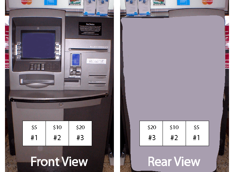 You could start a rabbit-hole of research to determine whether the numbers #1-2-3 start from left to right from the front or rear view, and build a test plan to test that; but you would only prove the machine does what is programmed to do. If the machine gets loaded from the back and the labels show #1-2-3 from left to right, the machine will be loaded with the $5 and $20 bills in the wrong location. The machine will dutifully spit out $20 to people who ask for $5 and $5 to people who ask for $20, even after the complicated test procedure gives you all passes.
An automated test makes it look like you are winning with your good-looking test report ($20 instead of $5), but the bank will probably lose money (relay fails to operate when it is supposed to) over the long run. The dynamic tester doesn’t need to do any research to make sure the right bills are dispersed, and they can complete the test in less time with a fancy test report.
Let’s look at the last link in the automated testing chain. The automated test needed to get input signals to receive inputs from the ATM, so the hopper connections were disconnected from the actual, in-service equipment (mapping a spare output) to get feedback to the test program. If you get a successful test with this method, do you even know if the hopper (actual trip output) is fully functional? No. There could be something mechanically wrong with the hopper that prevents it from operating correctly. Or wires could be crossed to disburse the wrong bills. The only sure way to test the actual hopper is to perform a full functional test. Why not just skip the in-between part and perform a fully functional test from the beginning?
You could start a rabbit-hole of research to determine whether the numbers #1-2-3 start from left to right from the front or rear view, and build a test plan to test that; but you would only prove the machine does what is programmed to do. If the machine gets loaded from the back and the labels show #1-2-3 from left to right, the machine will be loaded with the $5 and $20 bills in the wrong location. The machine will dutifully spit out $20 to people who ask for $5 and $5 to people who ask for $20, even after the complicated test procedure gives you all passes.
An automated test makes it look like you are winning with your good-looking test report ($20 instead of $5), but the bank will probably lose money (relay fails to operate when it is supposed to) over the long run. The dynamic tester doesn’t need to do any research to make sure the right bills are dispersed, and they can complete the test in less time with a fancy test report.
Let’s look at the last link in the automated testing chain. The automated test needed to get input signals to receive inputs from the ATM, so the hopper connections were disconnected from the actual, in-service equipment (mapping a spare output) to get feedback to the test program. If you get a successful test with this method, do you even know if the hopper (actual trip output) is fully functional? No. There could be something mechanically wrong with the hopper that prevents it from operating correctly. Or wires could be crossed to disburse the wrong bills. The only sure way to test the actual hopper is to perform a full functional test. Why not just skip the in-between part and perform a fully functional test from the beginning?
How Should You Test Protective Relays Summary
Testers who rely on automation without understanding what is happening in the background are essentially pulling the handle on a slot machine. The bells and whistles (test report passes) make it look like you’re winning, but your luck will run out eventually. I encourage you to use manual test methods for all your testing until the procedures actually sink in (you’ve done it so often that you could do it in your sleep), and then start playing with automation. All of your test procedures should follow this path.- Ask yourself, “What are the goals for this test?” and plan your test to meet those goals.
- Find out what the relay is supposed to do without looking at the settings in the relay. Try to get as far away from the settings as you can (coordination studies for overcurrent elements, line parameters for distance relays, setting engineer descriptions of operation or working sheets, documented, version-controlled settings from the design engineer)
- Review the site drawings and replace the CT/PT inputs with your test set as far from the relay as possible to test more of the circuit.
- Use in-service digital inputs whenever possible.
- Use the actual, in-use output contacts instead of spare-output simulations.
- Create realistic fault simulations on either side of the element pickup to prove the relay will ignore faults on the wrong side of pickup, and trip for faults on the operate side of pickup.
- If you can’t test an element without another element turning on, contact the design engineer to determine the scenarios that should operate without overlap. Usually the engineer doesn’t realize that an overlap has been set and will change the settings accordingly.
- Make sure your test will actually meet your goals. For example, does your CT secondary loop test prove that the current flows into the correct terminal? Many test plans that I’ve seen used will NOT prove polarity. Have someone switch the wires and see if your test plan will discover the change.
- Numeric keypad = Numpad.svg By Mysid (Self-made in Inkscape) [Public domain], via Wikimedia Commons
- Telephone keypad = https://upload.wikimedia.org/wikipedia/commons/7/7d/Telephone-keypad.png
Discover more from Valence Electrical Training Services
Subscribe to get the latest posts sent to your email.
Did you like this post?
You can share it with these links:
Read More Articles:
36th Annual Hands-On Relay School
thanks for info.