How to Test Breaker Failure Element Logic
I presented a “Testing Breaker Failure Schemes” paper at the 36th Annual Hands-On Relay School in 2019. This post is the second part of the paper that will give step-by-step test plans to help you test Breaker Failure Schemes. I highly recommend you read:
- Part 1 of the series first at “Introduction to Breaker Failure Schemes (50BF)“.
- Part 2 of the series at “How to Test Breaker Failure Schemes“
1. Testing Breaker Fail Scheme Logic
It has often been argued that there is no reason to test the relay logic if it is simply a copy of an existing scheme. I’ve found too many errors during maintenance tests to ever subscribe to that policy. Many of those problems essentially disabled the relay and prevented it from tripping the circuit breaker when faults are detected.
One of the errors that stands out was discovered during a maintenance test of a Breaker Failure Scheme. I had replaced all the CT and PT connections with my test-set, connected all operating outputs to my test-set, and simulated inputs with my test-set outputs by connecting them in parallel with the actual inputs. I was testing the Breaker Failure scheme as per the relay settings and everything was working properly because relays will do whatever they are told to do.
However, I happened to notice that another contact was operating during my Breaker Failure tests. It turned out to be a Re-Trip, which sends a last-ditch trip signal to the circuit breaker a few cycles after the initial trip was sent. The relay was programmed to send the Re-Trip, but I realized that its output contact was connected to the Breaker Fail Lockout Relay. The Breaker Fail Scheme was operating perfectly with a 15-cycle delay, but the Re-Trip would always trip the Breaker Fail Lockout in the real world before the Breaker Fail Timer had a chance to operate.
I contacted the utility personnel to report the problem, and they told me that they had just applied a new Breaker Failure Scheme to all their relays. They didn’t believe me at first because this scheme had been applied system-wide and surely someone had tested it thoroughly. They quickly changed their tune when I was able to get one of them to come on-site to demonstrate the problem. I learned to ALWAYS test the logic after that job.
Relay logic was created to replace physical wiring and relays inside a relay panel, which is why I’ve always been surprised by the lax attitude about relay logic testing in the industry. Which tests would you perform on a new switchgear installation? I’m hoping that you would do more than trust the point-to-point test from the switchgear manufacturer. A proper test of new switchgear should include a function test using the DC schematics for the switchgear. Your relay testing should also include a functional test of all elements from the equivalent of a schematic drawing.
The relay-logic equivalent of a switchgear schematic would be a version-controlled logic diagram, or a description of operation from the design engineer, or standards and practices for the location. I’m amazed that this documentation isn’t required for every relay installation. What would you do if you were told to perform a functional/commissioning test of the switchgear wiring, but they didn’t give you any schematics. I hope you would put your foot down and refuse; you should have the same conviction when it comes to relay logic.
A relay logic test is the same as a switchgear schematic test:
- Review the schematic diagram or description of
operation. - Function test each element in each path to
operate the relay outputs (Output contacts, LEDs, Front Panel Messages, Virtual
Outputs, etc.). - Make sure that all the functions are appropriate
for the location. - Make sure that everything makes sense.
A) Review the Logic Functions
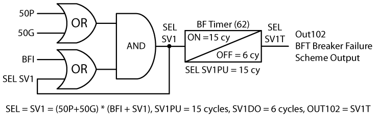
The following Figure displays the typical Breaker Failure Scheme logic we want to test, which could also be expressed in the math logic used by SEL relays as SV1 = (50P+50G) * (BFI + SV1) and SV1PU = 15 cycles:
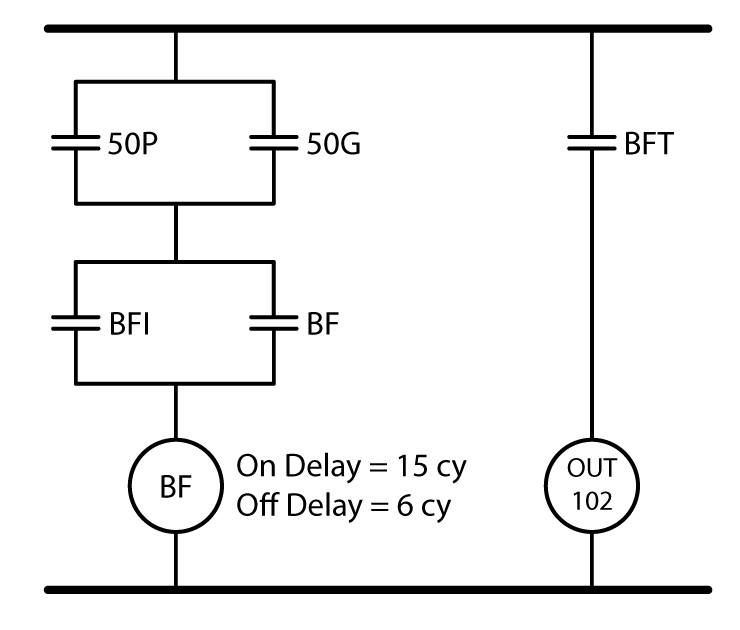
You can convert the logic into a schematic, which should be easier to understand and test. Replace all OR logic gates with contacts in parallel, all AND statements with contacts in series, all Timers with a timer relay, and all outputs with a relay. Figure 28 shows the equivalent schematic of a typical Breaker Failure Scheme:
How would you test this schematic drawing if it was part of a switchgear/commissioning test where you could touch and feel all of its parts?
Your test procedure might look something like:
- Close 50P and make sure nothing happens.
- Close BF. The BF relay should start timing and close the BF seal-in contact to keep the BF Scheme energized in case of a chattering contact.
- The BFT contact should close when the BF relay timer exceeds 15 cycles. Out102 should operate.
- Open the BFI contact. Nothing should happen because of the BF seal-in.
- Repeat the above procedure with 50G instead of 50P.
- Measure the time between the 50G opening and the BFT contact opening. It should match the 6 cycle Off Delay.
The last step is to make sure all of this makes sense from a functional perspective. In this case, the top row closes if phase or ground current flows, and the relay thinks the circuit breaker is closed. The timer starts if the BFI closes, and seals itself in to prevent mis-operation due to a chattering trip contact. The BFT occurs 15 cycles later. This is the functionality we were looking for.
You could also expand any logic to include a complete picture of the logic, as shown in Figure 29:
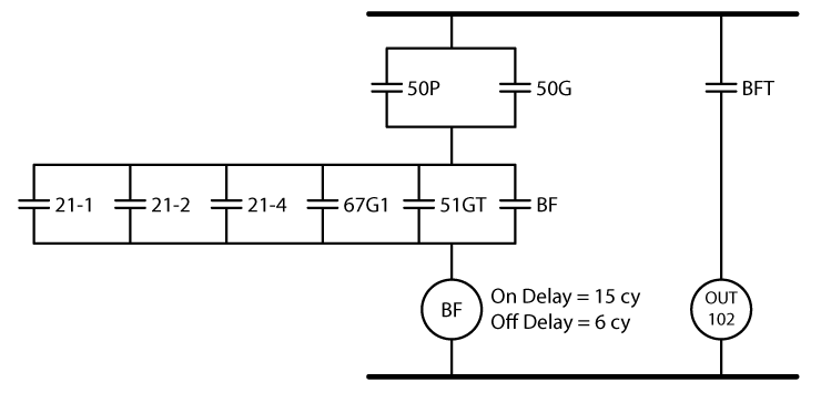
Figure 29: Schematic of Standard Breaker Failure Scheme Logic
B) Test the Logic Functions
It is possible to test this functionality by creating state simulations similar to the previous sections in this paper. The following steps will test the protection using a state for each logical step to prove the BF functionality:
- Create a Prefault state for a few cycles.
- Create a Close Circuit Breaker State:
- Apply three-phase or phase-phase current higher
than the 50P setting longer than the 62BFTD + the relay tolerance. - Enable an evaluation that checks to make sure
the BFT doesn’t operate.
- Apply three-phase or phase-phase current higher
- Inject a BFI Trip State that does not stop when
the BFT operates:- Check the BFI logic for a non-current element,
like Under/Over Voltage or Frequency. If so, create a fault state that operates
the BFI. Otherwise, inject a P-P or Three-Phase fault with current higher than
the 50P setting. - Create an assessment to measure the Trip time.
- Create an assessment to measure the time between
the Trip and BFT.
- Check the BFI logic for a non-current element,
- Create a Seal-In Check State:
- Remove the non-current fault or apply nominal
voltage and current 5% higher than the 50P setting. The BFI should drop out,
but the BF should seal itself in. - If the BFI does not drop out, press target
reset. - Create an assessment that checks that the BFT
contact stays closed.
- Remove the non-current fault or apply nominal
- Create an Off Delay Test State:
- Lower the current to 5% below the 50P setting.
The BFT should open. - Create an assessment that measures the time
between the start of this state and when the BFT opens.
- Lower the current to 5% below the 50P setting.
- Repeat with Phase-Ground currents.
You can add one or two states for any other logic inserted in the Breaker Failure Scheme to make it more secure or selective. You could also do all this testing manually if you do not need the documentation.
Design engineers can add more features into Breaker Fail Schemes and make some pretty complicated logic in their quest to solve more “What if?” questions. You could review the final logic in the relay and work out test scenarios, but I like to simply ask the design engineer “What is this supposed to do?” when the logic is complicated. I use their response to create a test plan that proves that the relay is doing what the design engineer intended it to do, instead of proving that the relay is simply doing what it is told.
Always get as far away as you can from
the actual settings when performing relay testing to ensure the relay works as
intended instead of as programmed; there is no guarantee that both are the same
unless you test it correctly.
2. Conclusion
Relay testing is much easier if you think about the element you are testing from the power system perspective and treat your test-set like a power system simulator. Figure 30 shows a complicated Breaker Failure Scheme that should make any relay tester tremble in their boots.
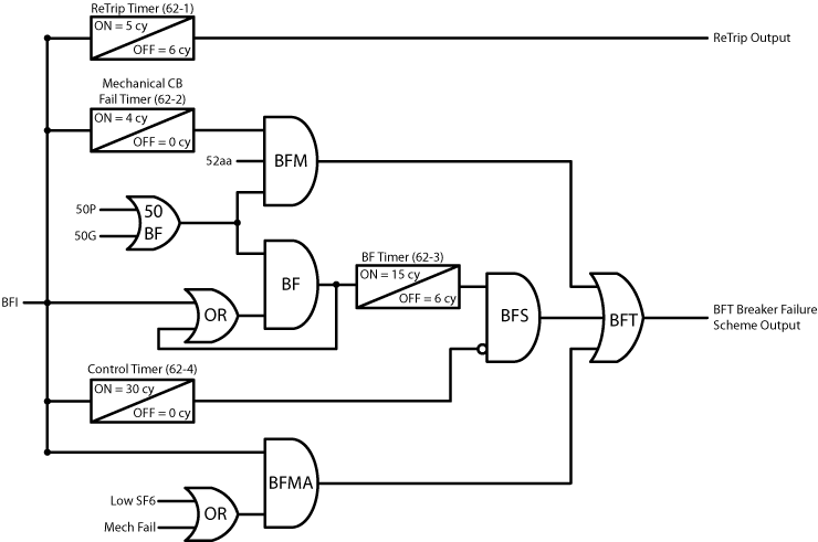
The SEL equivalent of the same scheme might look like:
- Out101 = Circuit Breaker Trip = TRIP
- Out102 = Breaker Fail Lockout Relay = SV2T +
SV3T + SV5 - Out103 = Circuit Breaker Re-Trip = SV1
- In103 = 52aa
- In104 = Low SF6
- In105 = Mech Fail
- SV1 = TRIP
- SV1PU = 5 cy
- SV1DO = 0 cy
- SV2 = IN103 * (50P2 + 50P3) * TRIP
- SV2PU = 4 cy
- SV2DO = 0 cy
- SV3 = (50P2+50G2) * (TRIP + SV1) * SV4T
- SV3PU = 15 cy
- SV3DO = 6 cy
- SV4 = TRIP
- SV4PU = 30 cy
- SV4DO = 0 cy
- SV5 = IN104 + IN105
- SV5PU = 0 cy
- SV5DO = 0 cy
Are your eyes rolling into the back of your head? You could reverse-engineer the relay logic to create a test plan, but the relay will do whatever it is programmed to do. Would you find the three mistakes in the logic if you simply reverse-engineered the settings to test the programmed functionality?
A better approach would be to contact the design engineer and ask them how the Breaker Fail Scheme is supposed to operate. The following description of operation describes the logic:
- If the relay sends a TRIP signal to the circuit breaker and initiates a BFI, a Re-Trip signal will be sent 3 cycles later to trip the circuit breaker via another output contact.
- There is no reason to wait for the full 62BFTD (15 cycles) if we can detect that something is wrong with the circuit breaker mechanism. If the relay detects that the circuit breaker mechanism has started the opening process and the circuit breaker still has not opened within the manufacturer’s specified time, we can issue a faster BFT via the following logic (BFM):
- If the relay sends a TRIP signal to the circuit breaker, AND
- the mechanism tries to open (52aa contact closes), AND
- the relay thinks the CB is still closed four cycles later because current is flowing through the circuit breaker higher than the current detector setting (50P2 OR 50G2), then
- the relay will send a Breaker Fail Lockout Trip to open all the adjacent circuit breakers via a BFT.
- A standard Breaker Failure Scheme is applied with a Control Timer to create a window of operation for the BFT. The Breaker Fail Signal can only be sent within 30 cycles after the BFI is detected to prevent standing trips on the adjacent circuit breakers after the fault has been cleared. The following describes the Breaker Failure Scheme (BFS) operating conditions:
- If a BFI signal is detected AND current is flowing through the circuit breaker higher than the current detector setting (50P2 OR 50G2), then the BF Timer (62-3) will start.
- The BFS logic seals itself in if the BFI signal chatters or bounces to ensure the BFS logic keeps running in case of contact failure.
- The BFS will issue a BFT if the circuit breaker remains closed (Current > 50P2 or 50G2) 15 cycles after the BFI signal as received. The BFS logic resets and opens the BFT output after 30 cycles to prevent standing trips on the power system after the event has passed.
- A BFT signal will also be sent if a BFI signal is received and something is wrong with the circuit breaker mechanism or insulation. A BFT trip will be sent with no intentional time delay if:
- the circuit breaker SF6 Low alarm is received and the relay detects a BFI signal, OR
- a circuit breaker mechanical alarm is detected and the relay receives a BFI signal.
The following test plans can test each part of the element using a power system perspective:
A) Re-Trip Test Procedure
You can test the Re-Trip Logic with the following test procedure:
- Connect Output103 to IN3 on your test-set.
- Run any of the TRIP timing tests that also issue
a BFI. - Measure the TRIP Time.
- Measure the Re-Trip Time.
- Calculate or measure the difference between the
two times.
The test will pass if you only look at the logic or relay settings,
but it fails if you look at the description of operation. That is the first
mistake in the logic. The time delay
does not match the engineer’s intent. You can only determine engineer’s intent
by asking the engineer, or via a description of operation.
B) Mechanical CB Fail (BFM) Test Procedure
You should test this protective function with the circuit breaker. Anything else will be a waste of time because you’ll never know if the circuit breaker is sending the correct signals.
- Make sure the 52aa contact is connected to the
relay. - Close the circuit breaker.
- Run any TRIP timing test that also issues a BFI,
and stop the test one cycle after the actual trip time. The BFT protection
should not have operated. - Run the same TRIP timing trip test that stops
seven cycles after the trip. The BFT protection should have operated in four to
seven cycles. - Block the 52aa contact and run the same TRIP
timing trip test that stops seven cycles after the trip. The BFT protection
should not operate.
Creating real simulations simplify your test plans and help you figure out if the logic makes sense for the application. Use the in-service equipment whenever possible.
C) Standard Breaker Fail Scheme (BFS) Test Procedure
This scheme is essentially the same as the previous sections, so you can apply any of the previous test procedures. However, they will all fail because of the second logic mistake. The SV3 logic is defined as SV3 = (50P2+50G2)*(TRIP + SV1)*SV4T, but it should be SV3 = (50P2+50G2)*(TRIP + SV1)*!SV4T. A one-character mistake changed the BFS time delay from 15 cycles to 30 cycles, and the Control Timer (62-4) has the opposite functionality from what was intended. The BFT will turn on and stay on after 30 cycles instead of turning on after 15 cycles and turning off after 30 cycles.
You can test the Control Timer by applying any of the BFT tests in
the previous section and adding a timer that starts when the BFI is received
and stops when the BFT output turns Off.
D) Circuit Breaker Alarm Breaker Failure (BGMA) Test Procedure
The circuit breaker has sensors that sends an alarm if the SF6 inside the circuit breaker is low. The circuit breaker controls will prevent it from opening if the SF6 level is dangerously low. It can also detect problems with the trip and close supply power. Attempting to open a circuit breaker is dangerous if these two problems already exist, so a fourth Breaker Failure Scheme is applied to bypass the Breaker Failure Timer. You can test this scheme with the following procedure:
- Simulate an SF6 low alarm at the circuit
breaker. The relay should receive the
alarm and nothing should happen.
The BFT would operate if you attempted this test with the provided logic settings because of the third logic mistake. This one was unintentional. I didn’t notice it until I reviewed this paper for the third time, and then decided to keep it.
The logic for this scheme is SV5 = IN104 + IN105, but it should be TRIP * (IN104 + IN105). This mistake would cause a catastrophic Breaker Failure Trip when the circuit breaker sent an alarm to warn the operators. This is a perfect example why you should always test the relay logic and make sure it makes sense for the application.
Would you want several circuit breakers to trip because someone opened the Trip Coil #1 DC circuit in a circuit breaker? That is exactly what would happen with this logic. I could test it as is and the relay would perform the function as programmed, but that doesn’t make it correct; even if I get all green checkmarks on my test sheet. You are the last line of defense in relay protection. If you don’t find a problem during commissioning, it probably won’t be found until someone gets hurt, the equipment is damaged, or a power system outage occurs.
Here is the complete BFMA test procedure.
- Simulate an SF6 low alarm at the circuit
breaker. The relay should receive the
alarm and nothing should happen. - Run a TRIP timing test that also initiates the
BFI. Measure the TRIP and the BFT time. The time delays should be nearly
identical. - Simulate a Mech Fail at the circuit
breaker. The relay should receive the
alarm and nothing should happen. - Run a TRIP timing test that also initiates the
BFI. Measure the TRIP and the BFT time. The time delays should be nearly
identical. - Clear all the CB alarms. Run a TRIP timing test
that also initiates the BFI that stops three cycles after the trip. The BFT should not operate. You could skip
this test because you should have already proven this part in your previous
tests.
If you start applying the principles in this paper to all of your tests, you’ll find that:
- You get a better understanding about the power
system. - You learn more about how your local system
functions. - Your testing time for each relay decreases
dramatically. - You are able to troubleshoot your test plans.
- You find more problems with the relays that help
prevent mis-operations and protect you and your co-workers. - Your day to day life becomes much less
stressful. There’s no testing task you
can’t handle. - People think you are much smarter than you
really are and start asking you to write papers and present papers at
conferencesJ
Happy Testing!
Discover more from Valence Electrical Training Services
Subscribe to get the latest posts sent to your email.
Did you like this post?
You can share it with these links:
Read More Articles:
Understanding the Great Leading vs. Lagging Power Debate