How to Test Breaker Failure Schemes
I presented a “Testing Breaker Failure Schemes” paper at the 36th Annual Hands-On Relay School in 2019. This post is the second part of the paper that will give step-by-step test plans to help you test Breaker Failure Schemes. I highly recommend you read Part 1 of the series first at “Introduction to Breaker Failure Schemes (50BF)“.
1. Testing Breaker Failure Schemes
Testing a Breaker Failure Scheme is pretty simple if you look at it from a power system perspective, instead of digging through all the individual relay nuances. From a power system perspective, the BF-element starts its timer when it detects a trip signal has been sent to the CB, and the CB is still closed after its timer expires. If you want to test a Breaker Failure Scheme: send a BFI signal while the BF-element thinks the breaker is closed and measure the time delay between the BFI and BFT.
We will use the following Breaker Failure Scheme Settings and test-set connections in all the example test plans:
- Phase Current-detector (50BFPP) = 1.0A
- Ground Current-detector (50BFGP) = 0.5A
- Breaker Failure Time (62BFTD) = 15 cycles
- BFI = All Trips and Relay Input101
- Trip = Relay Output101
- BFT =
Relay Output102 - 52 Status Simulation = Test-Set OUT1
- Trip From Other Relays = Test-Set OUT2
- Trip Signal from Relay = Test-Set IN1
- Breaker Fail trip (BFT) from Relay = Test-set
IN2 - Vnom = The Nominal System Voltage
- Vfault = Voltage during a fault
- Inom = Normal system current, or 0.00 Amps to
eliminate residual ground math. - STND PHROT = The Nominal System Phase Rotation
(ABC = 0°, -120°, 120°) - Bkr Open Time = The expected time between trip
and all three circuit breaker poles open.
All test plans assume that you have already performed the following tests:
- Determine if the BF Scheme uses contact status
or current to determine if the CB is closed. Use a test-set output (OUT1) to
simulate the CB status, if required. - Determine if the BFI signal uses a status input.
Connect a test-set output (OUT2) to the required input, if required. - Connect all the AC inputs used by the relay.
- Perform your standard acceptance tests:
- Power supply Check
- HMI display Check
- Relay Self-test
- Meter test
- Pulse all Outputs
- Verify
Inputs operate correctly
- Test all other elements inside the relay.
Here are several different ways to test a Breaker Failure Scheme once all the standard tests have been completed:
A) Manual Testing a Stand-Alone Breaker Failure Relay
Follow these steps to test a Stand-Alone Breaker Failure Relay manually:
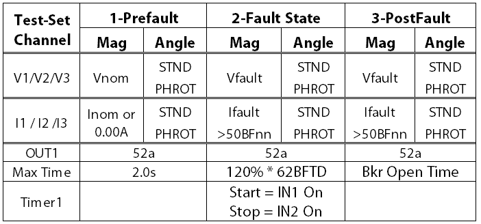
- Connect a test-set digital input (IN2) to the
relay’s BFT output contact (Output102). - Set up a normal Prefault State with nominal
current, nominal voltage, and a closed CB contact (OUT1), if required. - Set up a Fault State that:
- Initiates a BFI with test-set OUT2.
- Injects current greater than the Phase
BF Current-detector (50BFPP) settings, and/or keeps the test-set OUT1 contact
in the breaker-closed position. - Starts a timer that stops when the BFT
is detected by IN2. - Stops when the BFT is detected.
- Inject the Prefault State for a few seconds.
- Apply the Fault State.
- Compare the Timer setting to the expected time
delay (62BFTD). (The expected time is 15.00 cycles compared to the measured
time of 15.34 cycles = 2.9% error). Check the relay specifications for the
maximum absolute tolerance when dealing with a small number like 15 cycles.
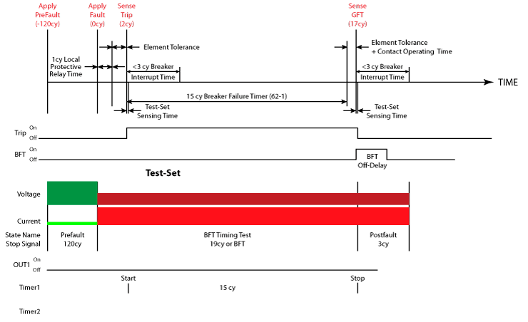
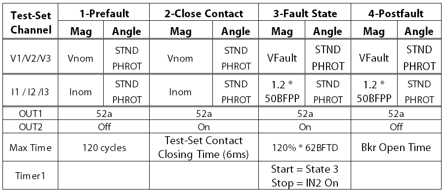
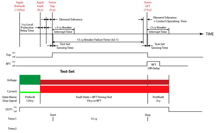
The following test plan shows the same plan where the expected time is 62BFTD + Test-set Contact Closing Time + Maximum Tolerance. The actual measured time was 15.78 cycles, including the 6ms test-set OUT1 closing time.
The hardest part of this test is accounting for your test-set’s contact closing time. For example, the MTS-5n00’s output closes 6ms after the close command is sent. You can add an extra state to account for the contact closing time, as shown below:
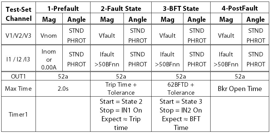
B) Manual Testing a Breaker Failure Element Inside a Standard Relay
You can use the previous stand-alone breaker failure relay steps if the BF-element uses a digital input in its BFI settings. Follow these steps to manually test a Breaker Failure Element in a relay with a BFI setting that includes other elements inside the same relay:
- Determine which other protective elements inside
the relay initiate a breaker failure. - Set up a normal Prefault State with nominal
current, nominal voltage, and a closed CB contact (OUT1), if required. - Set up a Fault State that:
- Applies a realistic fault (the voltage drops,
the current magnitude increases, and the current lags by 45-89°) that should
operate the trip output (Output101) and initiate a Breaker Fail (BFI). Make
sure the test current is greater than the Breaker Fail Current-detector
settings. The CB contact should remain closed, if required. - Starts a timer that stops when the Trip is
detected. - Stops the test when the Trip is detected.
- Applies a realistic fault (the voltage drops,
- Run the Prefault State for a few seconds and
then run the Fault State. Record the trip time (1.49 cycles). - Change the Fault state to:
- Start a timer that stops when the BFT is
detected. - Stops the test when the BFT is detected.
- Start a timer that stops when the BFT is
- Run the Prefault State for a few seconds and
then run the Fault State. Record the BFT time (16.50 cycles). - Subtract the Trip time from the BFT time to get
the measured Breaker Fail Time Delay (16.50 – 1.49 cycles = 15.01 cycles),
which bypasses all the additional time delays included in the Trip tolerance. - Compare the measured Breaker Fail Time Delay
(15.01 cycles) to the 62BFTD setting (15.0 cycles). Is the time delay within
the expected tolerance?
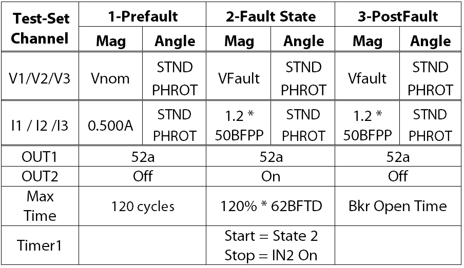
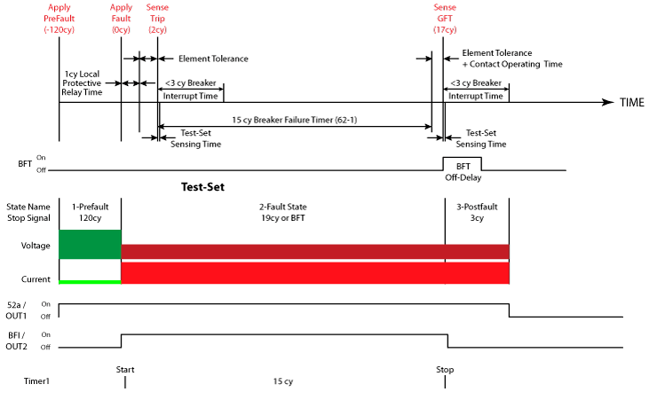
The following test plans show the two manual test procedures:
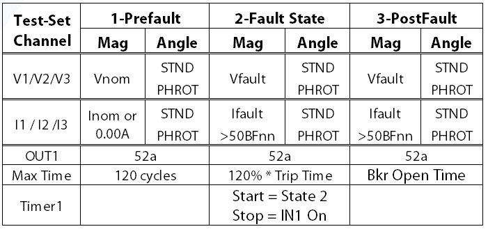
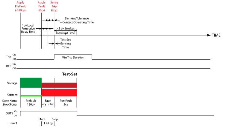
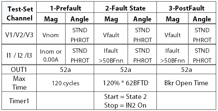
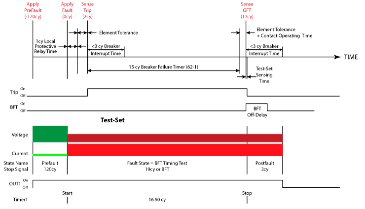
Figure 16: Manual Breaker Fail Element Test #2 Time Diagram
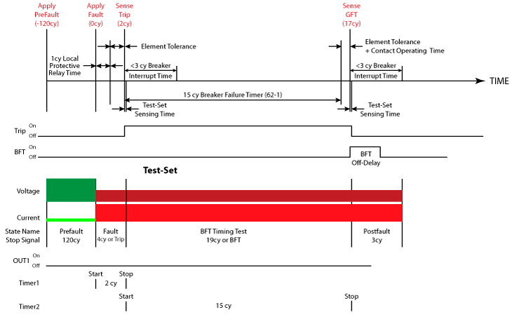
You can combine the two test procedures if you can create a timer
that measures the time between the Trip and BFT output contact operations with
the following modifications:
- Set up a Fault State that:
- Applies a realistic fault (the voltage drops,
the current magnitude increases, and the current lags by 45-89°) that should
operate the trip output (Output101) and initiate a Breaker Fail (BFI). Make
sure the test current is greater than the Breaker Fail Current-detector
settings. The CB contact should remain closed, if required. - Starts a timer when the Trip contact operates
and stops when the BFT is detected. - Stops the test when the BFT is detected.
- Applies a realistic fault (the voltage drops,
Run the Prefault State for a few seconds and then run the Fault State. Record the measured Timer time (14.99 cycles) and compare it to the 62BFTD setting.
The following test demonstrates the combined test procedure that merges the two test procedures if your test-set (MTS-5n00, Doble Protection Suite, Megger AVTS, or PowerDB) allows you to create a timer that can start when the Trip contact operates, and stops when the BFT contact operates.
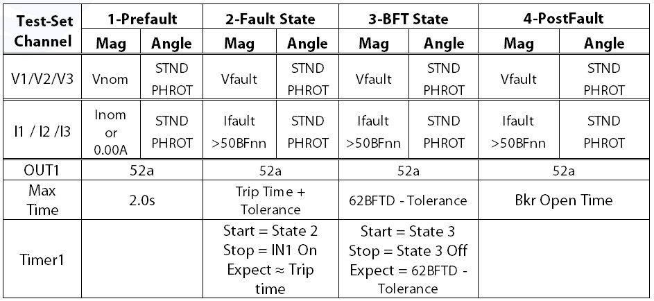
C) Dynamic Test for a Breaker Failure Element
Some test-sets don’t make it easy to record manual test results, or don’t have customizable timers (Doble Protection Suite, Enoserv RTS). This test procedure allows you to dynamically test the Breaker Failure Element using a 5% Under/Over dynamic test technique.
A dynamic test should always start with the 5% over state to prove that your test condition is set up correctly. This test is very similar to the previous BFT test, as per the following steps:
- Determine which other protective elements inside
the relay initiate a breaker failure. - Set up a normal Prefault State with nominal
current, nominal voltage, and a closed CB contact (OUT1), if required. - Set up a Fault State that:
- Applies a realistic fault (the voltage drops,
the current magnitude increases, and the current lags by 45-89°) that should
initiate a Breaker Fail (BFI). Make sure the test current is greater than the
Breaker Fail Current-detector settings. The CB contact should remain closed, if
required. - Starts a timer that stops when the Trip is
detected. - Transitions to the next state when a Trip is
detected.
- Applies a realistic fault (the voltage drops,
- Set up a Breaker Failure Test (BFT) State that:
- Applies the same voltages and currents from the
previous Fault State to simulate a breaker failure condition. - Starts a timer that stops when the BFT is
detected. - Transitions to the next state when a BFT is
detected.
- Applies the same voltages and currents from the
- Set up a Postfault State that:
- Applies the same voltages and currents from the
previous Fault State to simulate the actual breaker opening time. - Stops the test after the breaker opening time
- Applies the same voltages and currents from the
- Run the Prefault State for a few seconds and
then run the Fault State. Record the BFT time (16.50 cycles). - You now know that the actual 62BFTD is less than
your measured Breaker Failure Time delay (16.5 cycles). - The test conditions between dynamic tests should
only have one change to ensure you are testing what you think you are testing.
We’re testing the time delay, so you should duplicate the previous Fault State
and change the State 2 Max Time to the 62BFTD (15 cycles) – the max tolerance
(Rule of thumb for small numbers = 3 cycles) for a 12 cycle delay in our test
case. You can reduce the tolerance if you wish to gain more accuracy, but the
relay may trip if you perform a test within the expected tolerance. - The evaluation should be changed to expect No
Operation. - Run the Prefault State for a few seconds and
then run the Fault State. The BFT should not operate because the 62BFTD timer
should not time out within 12 cycles. If this is the case, the 60BFTD is somewhere
between 12 – 16.5 cycles. Any number between those two numbers passes, so there
is no reason to continue testing if both tests pass.
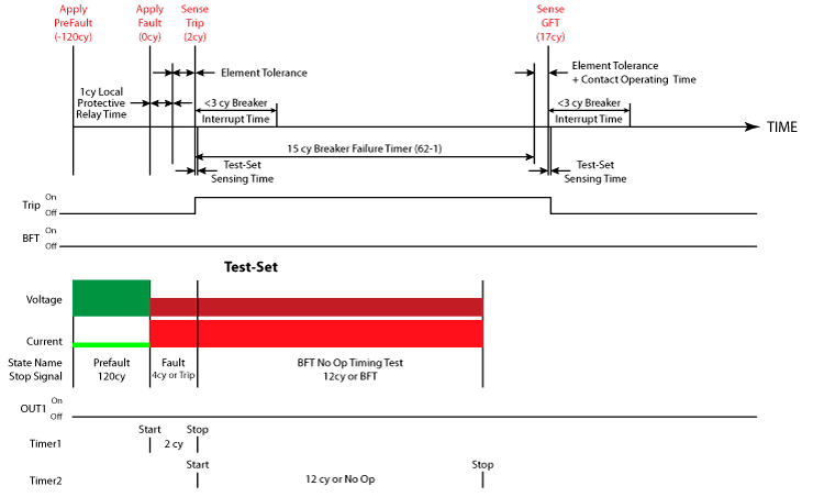
The following test plans show the two Dynamic test procedures:
2. Testing Breaker Failure Schemes with State Simulations
State simulations allow you to control every aspect of a test, which is why they are my default test procedure. Sometimes the test-set macros can get in the way of realistic fault simulations; like Doble and Enoserv RTS tests that do not inject Prefault values between pulses, or some Manta MTS productivity modes that are missing the channels necessary for complex tests, or Omicron Test Universe’s hidden errors that prevent you from running tests. I immediately switch to the following test modes when I realize that a test isn’t running the way I want it to, and I find myself in a battle with the test-set software instead of testing relays:
- Doble’s Protection Suite State Simulation Test
Step - Enoserv’s RTS Logic/Scheme Test
- Manta’s Manual Test Menu
- Omicron’s Test Universe State Sequencer Test
Module
You could use any of these modules to perform the tests in the previous section, but each of these test-sets have different operating characteristics that require slight tweaks to perform a Breaker Failure dynamic pickup/timing test. The following sections detail the specific test-set requirements to build a dynamic test procedure that can be applied to any element in any relay.
A) Doble’s Protection Suite State Simulation Testing
Doble’s Protection Suite software allows you to set all of the state transitions to move to the next state if the timer expires, or jump to another state if the contact operates. We can create a Postfault state at the end of the test procedure that the test will jump to if the BFT operates in any state.
You can set a timer that starts when the 5% Over Trip State starts, and stops when the relay output operates. The evaluation is set to pass if the timer falls within the timing accuracy of the element. If the element operates in any state other than the Pickup state, the test fails because the timer will be bypassed.
The following test procedure reverses the previous procedures to obtain a Breaker Fail Trip evaluation with one timer:
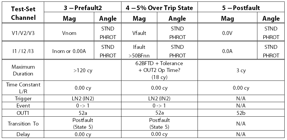
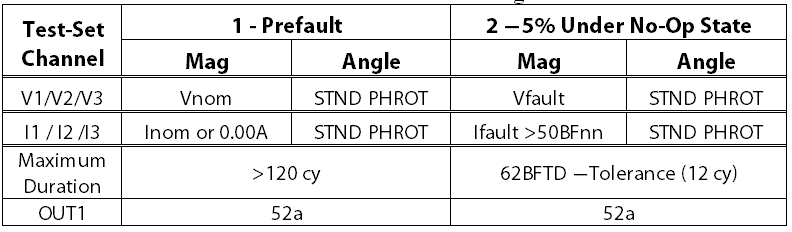
- Create five States in the State Simulation Test.
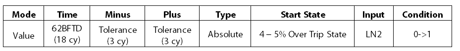
- Create a
Timer with the following settings:- Expected Result/Mode = Value.
- Expected Result/Time = Expected 62BFTD (15
cycles). - Tolerance/Minus/Plus = Relay tolerance +
test-set OUT2 closing time, if required (Rule of thumb for small numbers = 3
cycles). - Tolerance/Type = Absolute.
- Start State = 5% Over Trip State.
- Stop Event/Stop State = LN2 (IN2 / Output 2).
- Stop Event/Condition = 0 ->1.
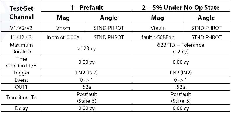
- Set a Prefault State with:
- Nominal current, nominal voltage, and a closed
CB contact (OUT1), if required. - Maximum Duration = 2.00s, or longer.
- Trigger = LN2 (IN2).
- Event = 0 -> 1.
- Transition To = Postfault State, which will be
the last state in the test. - Delay = 0.0000s.
- If the BFT operates in this state, it will jump
to the last state and skip all the timers.
- Nominal current, nominal voltage, and a closed
- Set a 5% Under No-Op State with:
- A realistic fault (the voltage drops, the
current magnitude increases, and the current lags by 45-89°) that should
initiate a Breaker Fail (BFI). Make sure the test current is greater than the
Breaker Fail Current-detector settings. The CB contact should remain closed, if
required. - Maximum Duration = 62BFTD (15 cycles) – the max
tolerance (Rule of thumb for small numbers = 3 cycles), which would be a 12
cycle delay in our test case. - Trigger = LN2 (IN2).
- Event = 0 -> 1.
- Transition = Postfault State, which will be the
last state in the test. - Delay = 0.0000s.
- If the BFT operates in this state, it will jump
to the last state and skip all the timers.
- A realistic fault (the voltage drops, the
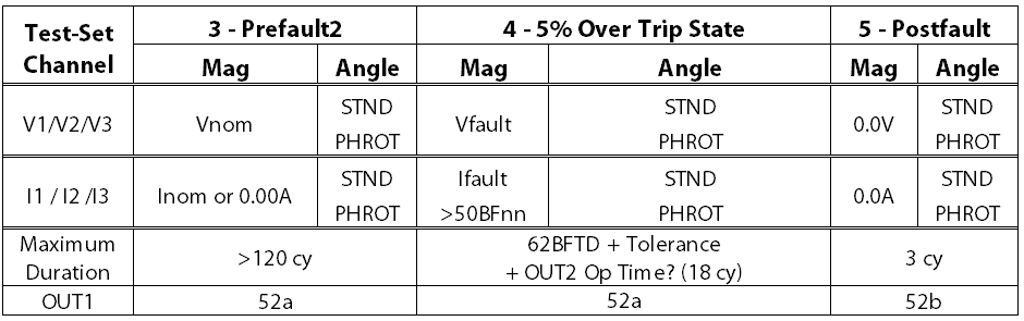
- Set a Prefault2 State with:
- Nominal current, nominal voltage, and a closed
CB contact (OUT1), if required. - Maximum Duration = 2.00s, or longer.
- Trigger = LN2 (IN2).
- Event = 0 -> 1.
- Transition To = Postfault State, which will be
the last state in the test. - Delay = 0.0000s.
- If the BFT operates in this state, it will jump
to the last state and skip all the timers.
- Nominal current, nominal voltage, and a closed
- Set up a 5% Over Trip State with:
- A realistic fault (the voltage drops, the
current magnitude increases, and the current lags by 45-89°) that should
initiate a Breaker Fail (BFI). Make sure the test current is greater than the
Breaker Fail Current-detector settings. The CB contact should remain closed, if
required. - Maximum Duration = 62BFTD (15 cycles) + the max
tolerance (Rule of thumb for small numbers = 3 cycles), which equals 18 cycles
in our test case. - Trigger = LN2 (IN2).
- Event = 0 -> 1.
- Transition = Postfault State, which will be the
last state in the test. - Delay = 0.0000s
- If the BFT operates in this state, the timer
will start and record the BFT time.
- A realistic fault (the voltage drops, the
- Set up a Postfault State that:
- applies zero volts and amps for a few cycles to
use as a placeholder for the test, or - applies the same currents and voltages from the
trip state with a Maximum Duration set at the expected CB trip time to give the
relay time to display the correct targets, or - applies nominal voltage for 30-60 seconds to
give you time to review the targets before other elements, like undervoltage,
have a chance to operate.
- applies zero volts and amps for a few cycles to
- Run the test. If the BFT operates in any state
before the 5% Over Trip State, the test-set will jump to the last state and
bypass the timer, which means the test should fail. If the BFT operates in the
5% Over Trip State, the timer should start and record the BFT trip time. If the
Timer evaluation passes, you know that the time delay is between 5% Under No-Op
State Maximum Duration setting and the measured timer delay. Any number between those two values should be
a pass, so your time test is complete.
The following Figure displays the test plan:
Timer Settings
B) Enoserv’s RTS Logic/Scheme Test
Enoserv RTS’ Logic/Scheme Tests can only move forward from one state to the next, and the trigger to the next state can only be a contact or time-out. You can only make one evaluation per input, so you can either split the test into two as described in previous sections, or jumper IN2 and IN3 on the test-set so that the BFT will operate both test-set inputs.
You can build a test with two timers and five states, as per the following description:
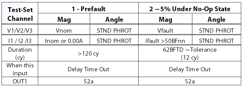
- Set a Prefault State with:
- Nominal current, nominal voltage, and normal
phase rotation. - Duration (cy) = 120 cy.
- State to Advance to the next state when this
input = Delay Time. - Output 1 = a closed CB contact (OUT1), if
required.
- Nominal current, nominal voltage, and normal
- Set a 5% Under No-Op State with:
- A
realistic fault (the voltage drops, the current magnitude increases, and the
current lags by 45-89°) that should initiate a Breaker Fail (BFI). Make sure
the test current is greater than the Breaker Fail Current-detector settings. - Duration (cy) = 62BFTD (15 cycles) – the max
tolerance (Rule of thumb for small numbers = 3 cycles), which would be a 12
cycle delay in our test case. - State to Advance to the next state when this
input = Delay Time. - Output 1 = a closed CB contact (OUT1), if
required.
- A
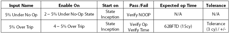
- Go to User Options to set up a no-operation
evaluation on Input 02 to perform one-half of the dynamic test, as per the
following instructions:- Input Name = BFT
- Enable on = 5% Under No-Op State
- Start on = State Inception
- Stop On = Open -> Close
- Pass/Fail = Verify NOOP
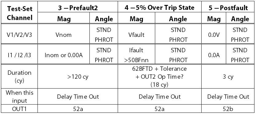
- Set a Prefault2 State with:
- Nominal current, nominal voltage, and normal
phase rotation. - Duration (cy) = 120 cy.
- State to Advance to the next state when this
input = Delay Time. - Output 1 = a closed CB contact (OUT1), if
required.
- Nominal current, nominal voltage, and normal
- Set up a 5% Over Trip State with:
- A realistic fault (the voltage drops, the
current magnitude increases, and the current lags by 45-89°) that should
initiate a Breaker Fail (BFI). Make sure the test current is greater than the
Breaker Fail Current-detector settings. - Duration (cy) = 62BFTD (15 cycles) + the max
tolerance (Rule of thumb for small numbers = 3 cycles), which equals 18 cycles
in our test case. - State to Advance to the next state when this
input = Delay Time. - Output 1 = a closed CB contact (OUT1), if
required.
- A realistic fault (the voltage drops, the
- Go to User Options to set up a time evaluation
on Input 03 to perform the second half of the dynamic test, as per the
following instructions:- Input Name = BFT
- Enable on = 5% Over Trip State
- Start on = State Inception
- Stop On = Open -> Close
- Pass/Fail = Verify Op & Verify Time
- Expected Op Time = Expected 62BFTD (15 cycles)
- Tolerance = Absolute tolerance plus test-set
OUT2 closing time, if required (Rule of thumb for small numbers = 3 cycles)
- Set up an optional Postfault State that:
- applies the same currents and voltages from the
trip state with a Maximum Duration set at the expected CB trip time to give the
relay time to display the correct targets, or - applies nominal voltage for 30-60 seconds to
give you time to review the targets before other elements, like undervoltage,
have a chance to operate.
- applies the same currents and voltages from the
- Run the test. If the BFT operates in the 5%
Under No-Op State, the test-set Input 02 evaluation will fail the Expect NOOP
evaluation. If the BFT operates in the 5% Over Trip State, the timer should
start and record the BFT trip time. If the Timer evaluation passes, you know
that the time delay is between 5% Under No-Op State Maximum Duration setting
and the measured timer delay. Any number
between those two values should be a pass, so your time test is complete.
The following Figure displays the test plan:
User Options Settings
C) Manta’s Manual Test Menu Testing
Manta’s front panel is like the state simulation programs from other software packages. Any relay contact operation stops the test because all inputs are set to go to a Postfault state by the factory. Postfault is disabled by default, so the test simply stops when an input operates. You could manipulate the settings to mimic any test in this paper that does not use a No Operation evaluation.
A dynamic test runs through a series of States that shouldn’t operate the BFT output. If the element operates in any state that should not trip, the test fails because the test stops before the timer has a chance to start. Then a timer starts when the 5% Over Trip State starts and stops when the relay output operates. The evaluation is set to pass if the timer falls within the timing accuracy of the element.
Use the following test plan to create a dynamic manual test using Manta’s Manual Test Menu:
- Go to Advanced Settings and change the following
settings:- Maximum Fault Duration Enabled = cycles
- Number of Fault States = 4
- Disable the BFT (IN1) contact sensing by
removing one wire from IN1, or going to Advanced Settings/Set up I/O and
Timers/Configure State Control and changing the #1 Go To State setting to Same
State. - Go to Advanced Settings/Set up I/O and Timers/Configure
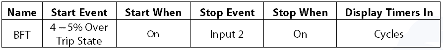
Timers and Counters to create a Timer with the following settings:- Name = BFT
- Start Event = Fault 3
- Start When = On
- Stop Event = Input 2
- Stop When = On
- Display Timer in = Cycles
- Choose the correct Fault Type in the Manual Test
Menu - Remove unnecessary information from the screen
using the Set up Display Menu - If circuit breaker status changes are required,
go to Advanced Settings/ Set up I/O and Timers/Configure Outputs and:- Change #1 Function to Custom
- Use Configure Custom Output States menu to set
the output state, as per the descriptions in each state below.
- Set a Prefault State with:
- Nominal voltage, nominal current, and phase
angles. - Maximum Duration = 120.000 cyc, or longer.
- Output 1 = a closed CB contact (OUT1), if
required. - If the BFT operates in this state, the test will
stop and the timer will not start.
- Nominal voltage, nominal current, and phase
- Set a 5% Under No-Op State with:
- A realistic fault (the voltage drops, the
current magnitude increases, and the current lags by 45-89°) that should
initiate a Breaker Fail (BFI). Make sure the test current is greater than the
Breaker Fail Current-detector settings. - Maximum Duration = 62BFTD (15 cycles) – the max
tolerance (Rule of thumb for small numbers = 3 cycles), which would be a 12
cycle delay in our test case. - Output 1 = a closed CB contact (OUT1), if
required. - If the BFT operates in this state, the test will
stop and the timer will not start.
- A realistic fault (the voltage drops, the
- Set a Prefault2 State with:
- Nominal voltage, nominal current, and phase
angles. - Maximum Duration = 120.000 cyc, or longer.
- Output 1 = a closed CB contact (OUT1), if
required. - If the BFT operates in this state, the test will
stop and the timer will not start.
- Nominal voltage, nominal current, and phase
- Set up a 5% Over Trip State with:
- A realistic fault (the voltage drops, the
current magnitude increases, and the current lags by 45-89°) that should
initiate a Breaker Fail (BFI). Make sure the test current is greater than the
Breaker Fail Current-detector settings. - Maximum Duration = 62BFTD (15 cycles) + the max
tolerance (Rule of thumb for small numbers = 3 cycles), which equals 18 cycles
in our test case. - Output 1 = a closed CB contact (OUT1), if
required. - If the BFT operates in this state, the timer
will start and record the BFT time.
- A realistic fault (the voltage drops, the
- Set up an optional Postfault State that:
- applies the same currents and voltages from the
trip state with a Maximum Duration set at the expected CB trip time to give the
relay time to display the correct targets, or - applies nominal voltage for 30-60 seconds to
give you time to review the targets before other elements, like undervoltage,
have a chance to operate.
- applies the same currents and voltages from the
- Run the test. If the BFT operates in any state
before the 5% Over Trip State, the test-set stops before the timer can start,
which means the test should fail. If the BFT operates in the 5% Over Trip
State, the timer should start and record the BFT trip time. If the Timer
evaluation passes, you know that the time delay is between 5% Under No-Op State
Maximum Duration setting and the measured timer delay. Any number between those two values should be
a pass, so your dynamic test is complete.
The following Figure displays the test plan:
Advanced Settings
- Maximum Fault Duration Enabled = cycles.
- Number of Fault States = 4.
- Advanced Settings/Set up I/O and
Timers/Configure State Control and change the #1 Go To state to Same State. - Advanced Settings/ Set up I/O and
Timers/Configure Outputs #1 = Custom
Manual Test Menu Settings
Advanced Settings/Set up I/O and Timers/Configure Timers Settings
D) Omicron’s State Sequencer Test
The Omicron Test Universe software requires you to go through all fault states in the order specified. Therefore, you should set the trigger for each state to move forward whenever the time delay is exceeded, or the contact closes, whichever comes first.
Set one Time Assessment to start when the 5% Under No-Op State begins, and to stop when the next state starts. Set the Tnom to be the 5% Under No-Op State time delay with a very small tolerance (+/- 0.001s). The Assessment passes if the relay does not operate. The assessment fails if the relay operates and the test goes to the next state faster than the No-Pickup state time delay. You may be able to use the State Assessment section to create a No Operation evaluation instead.
A second time assessment is set like a traditional time test that starts when the 5% Over Trip State starts, and stops when the relay output operates. The evaluation passes if the timer falls within the timing accuracy of the element. Make sure you enable the test-set IN/BFT sensing via the Hardware Configuration menu for all tests.
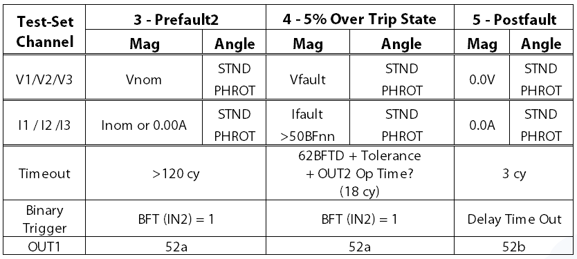
You can build a test with two timers and five states, as per the following description:
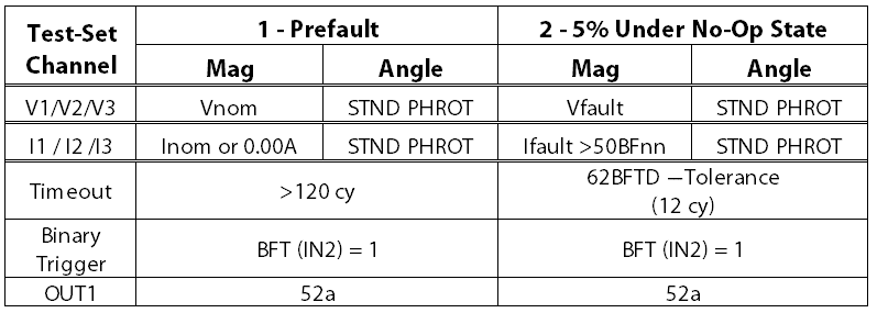
- Set a Prefault State with:
- Nominal current, nominal voltage, and normal
phase rotation. - Use binary trigger condition as specified below
= checked. - Timeout = Checked & =>120.00 cycles.
- Input 2 = 1.
- Bin. Out 1= a closed CB contact (OUT1), if
required.
- Nominal current, nominal voltage, and normal
- Set a 5% Under No-Op State with:
- A realistic fault (the voltage drops, the
current magnitude increases, and the current lags by 45-89°) using the Fault
Values Set Mode that should initiate a Breaker Fail (BFI). Make sure the test
current is greater than the Breaker Fail Current-detector settings. - Use binary trigger condition as specified below
= checked - Timeout = Checked & 62BFTD (15 cycles) – the
max tolerance (Rule of thumb for small numbers = 3 cycles), which would be a 12
cycle delay in our test case. - Input 2 = 1
- Bin. Out 1= a closed CB contact (OUT1), if
required.
- A realistic fault (the voltage drops, the
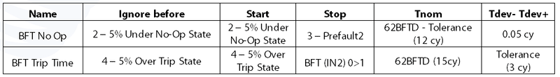
- Go to Time Assessments to set up a no-operation
evaluation and perform one-half of the dynamic test, as per the following
instructions:- Name = BFT No Op.
- Ignore before = 5% Under No-Op State.
- Start = 5% Under No-Op State.
- Stop = 3 – Prefault2.
- Tnom = 5% Under No-Op State Timeout (12 cycles).
- Tdev- = 0.5 cy.
- Tdev+ = 0.5 cy.
- Set a Prefault2 State with:
- Nominal current, nominal voltage, and normal
phase rotation. - Use binary trigger condition as specified below
= checked. - Timeout = Checked & =>120.00 cycles.
- Input 2 = 1.
- Bin. Out 1= a closed CB contact (OUT1), if
required.
- Nominal current, nominal voltage, and normal
- Set up a 5% Over Trip State with:
- A realistic fault (the voltage drops, the
current magnitude increases, and the current lags by 45-89°) using the Fault
Values Set Mode that should initiate a Breaker Fail (BFI). Make sure the test
current is greater than the Breaker Fail Current-detector settings. - Use binary trigger condition as specified below
= checked. - Timeout = Checked & 62BFTD (15 cycles) + the
max tolerance (Rule of thumb for small numbers = 3 cycles), which equals 18
cycles in our test case. - Input 2 = 1.
- Bin. Out 1= a closed CB contact (OUT1), if
required.
- A realistic fault (the voltage drops, the
- Go to Time Assessments to set up time evaluation
to perform the second half of the dynamic test, as per the following
instructions:- Name = BFT Trip Time.
- Ignore before = 5% Over Trip State.
- Start = 5% Over Trip State.
- Stop = BFT (IN2) 0>1.
- Tnom = Expected 62BFTD (15 cycles).
- Tdev- = Absolute tolerance plus test-set OUT2
closing time, if required (Rule of thumb for small numbers = 3 cycles). - Tdev+ = Absolute tolerance plus test-set OUT2
closing time, if required (Rule of thumb for small numbers = 3 cycles).
- Set up an optional Postfault State that:
- applies the same currents and voltages from the
trip state with a Maximum Duration set at the expected CB trip time to give the
relay time to display the correct targets, or - applies nominal voltage for 30-60 seconds to
give you time to review the targets before other elements, like undervoltage,
have a chance to operate.
- applies the same currents and voltages from the
Run the test. If the BFT operates in the 5% Under No-Op State, the test-set’s BFT No Op evaluation will fail because the time in 5% Under No-Op State would be shorter than the expected time. If the BFT operates in the 5% Over Trip State, the timer should start and record the BFT trip time. If the Timer evaluation passes, you know that the time delay is between 5% Under No-Op State Maximum Duration setting and the measured timer delay. Any number between those two values should be a pass, so your time test is complete.
The following Figure displays the test plan:
User Options Settings
Discover more from Valence Electrical Training Services
Subscribe to get the latest posts sent to your email.
Did you like this post?
You can share it with these links:
Read More Articles:
How to Test Breaker Failure Element Logic