No products in the cart.
I Want to Know How a High Impedance Differential Scheme Works
We received this question from the Ask Chris form at relaytraining.com. Follow this link to ask your own question and it might appear in a future blog post.
High Impedance Differential Scheme Testing
High impedance differential relays are some of the easiest relays to test.
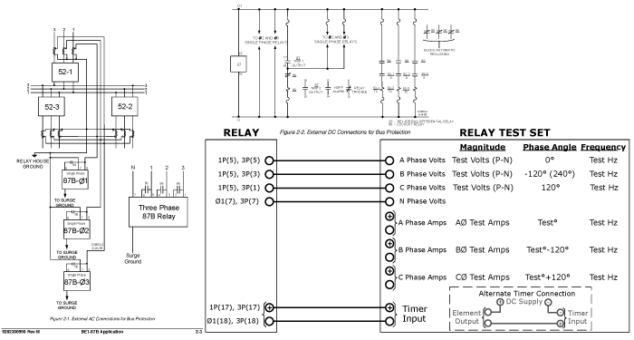
- Isolate the relay from the trip circuit and voltage inputs.
- Connect your test-set voltage channel across the relay AC input.
- Connect your test-set sensing input to the relay trip output.
- Perform an overvoltage pickup test.
- Perform an overvoltage timing test. (Be aware that definite time elements typically have a curve. We discuss this in detail in the How to Test Protective Relays Online Seminar.)
- Return the relay to service.
(We discuss the details of the generic test procedures involved in The Relay Testing Handbook: Principles and Practice and the How to Test Protective Relays Online Seminar.)
The only thing you really need to be concerned with is that many high impedance differential relays have contacts applied in parallel with the voltage input like the external ones shown in the previous drawing. These contacts short the voltage inputs when the relay operates to help prevent high voltages in the circuit. From your test-set’s perspective, a high impedance load has suddenly changed to a short-circuit that overloads the channel. You may have to get creative to find out what voltage was applied before the overload, depending on how your test-set handles voltage channel overloads.
High Impedance Differential Scheme Basics
How the scheme works is more complicated than it looks. I thought this would be a pretty easy answer. It turns out that there are a couple of assumptions that aren’t explained very well in most textbooks, papers, and online explanations. I had a lot of help with this question from Rodney Hughes at Rod Hughes Consulting Pty. Ltd. (www.rodhughesconsulting.com). His explanations are much more comprehensive than this one and I highly recommend you visit his website to really dig into it.
We discuss generator and transformer differential protection in The Relay Testing Handbook: Principles and Practice, where we review how tap and slope characteristics can compensate for:
- different voltage classes,
- different CT ratios,
- different CT accuracy classes,
- and phase shifts on either side of the protected device.
We can apply the same principles to buss protection as shown in the following diagram:
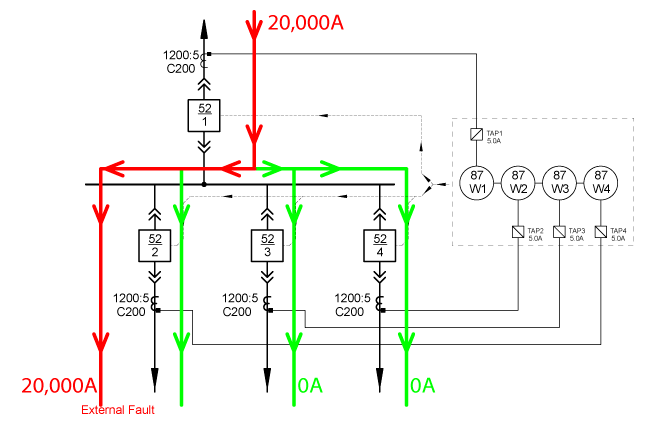
This scheme can protect a buss, but we have some new concerns that must be addressed:
- What happens when we want to add a feeder to the buss and there aren’t enough inputs to the relay?
- There are a lot of calculations involved in traditional differential protection that add time before the relay can trip. We want the relay to trip as fast as possible.
- Generators and transformers have built-in current limiting characteristics that aren’t found in busses. (CT saturation is much more likely to occur in buss faults.)
High impedance differential protection can help with all of these problems, but first we need to apply some rules:
- All CT’s connected to the high impedance differential must have the same:
- Ratio
- Accuracy class
- Construction, or operating properties
- All the CT’s must be connected in parallel
- The point where all the CTs tie together should be equidistant from all CTs
- The burden rating/saturation voltage must be sized appropriately
- No other equipment can be connected to the CT outputs
Once we apply all of the rules, our high impedance differential protection scheme starts to look like the following diagram:
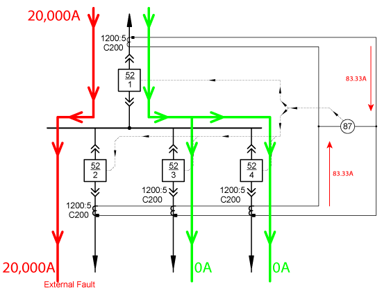
This scheme is the example used in Application Guidelines for Microprocessor-Based, High-Impedance Bus Differential Relays (Stanley E. Zocholl and David Costello, Schweitzer Engineering Laboratories, Inc.). The 87 relay was initially a simple overcurrent relay when a 20,000A fault current was applied. They measured the following current through the relay:
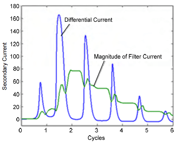
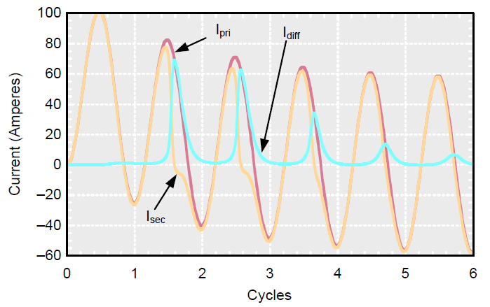
That’s a lot of differential current! But it’s not sinusoidal. Actually, it looks a lot like the differential current (Idiff) in a saturated CT as shown in this graph from Considerations for Using High-Impedance or Low-Impedance Relays for Bus Differential Protection (Ken Behrendt, David Costello, and Stanley E. Zocholl Schweitzer Engineering Laboratories, Inc.)
A stabilizing resistance was added in series with the overcurrent element to create a high impedance differential scheme as shown below:
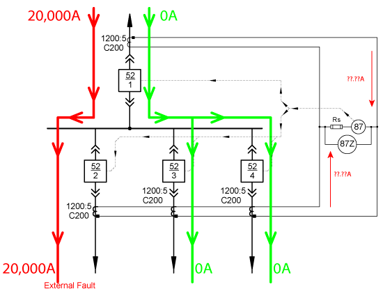
Can you guess what happens to the current after we add the stabilizing resistor? If we apply Ohm’s Law, 160A * 2000Ω = 320,000V across the 87Z element. That can’t be right, can it?
The following graph shows what happened after the resistor was added to the circuit.
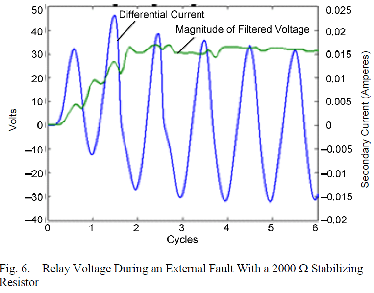
Where did all that current go? This introduces a concept that doesn’t have a clear answer in textbooks or papers. Here are some explanations:
- “To improve security during external faults, we add a large stabilizing resistance in series with the low-impedance overcurrent relay. This reduces the differential current to a milliamp level and allows the secondary current to flow between the CTs.” Application Guidelines for Microprocessor-Based, High-Impedance Bus Differential Relays (Stanley E. Zocholl and David Costello, Schweitzer Engineering Laboratories, Inc.)
- “… a high-impedance relay unit… tends to force the false-differential currents through the current transformers rather than the relay operating coil.” Applied Protective Relaying (1979 Westinghouse Electric Corporation)
- “This scheme loads the CTs with a high-impedance to force the error differential current through the CTs instead of the relay operating coil.” Protective Relaying: Principles and Applications Second Edition (J. Lewis Blackburn)
Other papers and textbooks refer to this differential current as the “slush” or “spill” currents. However, I don’t think they mean the sinusoidal differential current caused by CT mismatch. I think they mean the non-sinusoidal currents that occur when CTs saturate. If a CT saturates, the normally high, non-sinusoidal currents will find the shortest path home. 2000Ω is a much higher impedance than the CT secondary circuits around it because the current is flowing in the same direction during an external fault. This means the non-sinusoidal currents will find a path through the CT secondary currents instead of the differential circuit.

Differential current still flows through the differential circuit, but it is the normal sinusoidal differential current created by CT mismatch.
A high impedance differential relay can have a current setting that monitors the current through the 87 element. In this case, the setting must be higher than 0.016Arms (peak * 0.707 = 0.022 * 0.707), otherwise the relay will trip for a fault outside the zone of protection as per the measurements in the example.
The high impedance element can also be set in voltage. The voltage measured by the 87Z element is 32V (0.016A * 2000Ω). This means the 87Z setting must be greater than 32V or the relay will trip during faults outside the zones of protection. (Both settings should be much higher. We’ll cover what the setting should be in the next post about high impedance differential protection.)
Some high impedance differential relays are actually current relays that use Ohm’s Law to create a setting in volts.
What happens if the fault is inside the zone of protection?
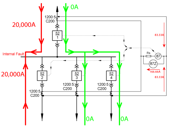
In this situation, the current flowing into the zone of protection doesn’t equal the current flowing out. The secondary currents aren’t mostly cancelling each other out like they were in an external fault; they are both pushing in the same direction and looking for the lowest impedance path home. In this case, the internal impedances of the CTs are acting as open-circuits (more on this in the next post); so the CTs try to push current through the 2000Ω resistor. 166.66A through a 2000Ω resistor is 333,320V. The CTs probably won’t be able to generate 333,320V, but the secondary voltage can theoretically rise to the system voltage.
The system voltage (or 333,320V) is probably a little higher than the CT saturation voltage; so the CTs will start to saturate immediately. The relay won’t be looking at the saturation differential current we showed you earlier; it will see something like the red line in the following graph:
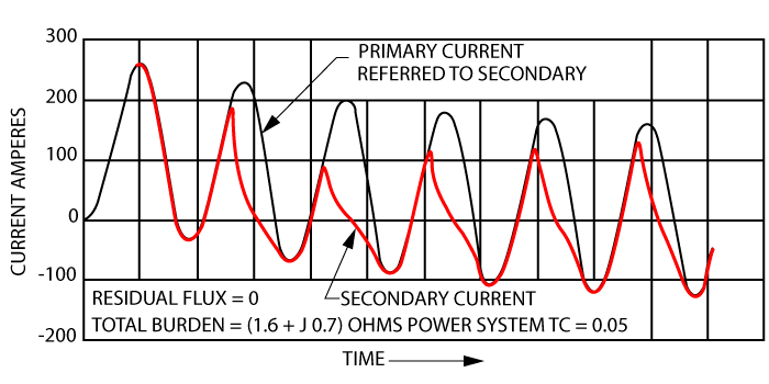
This waveform shape can cause problems and time delays with digital relays that must measure the voltage/current input, analyze the waveform, and then evaluate whether to trip, or not. This can create extra time between the fault inception and the relay operation that doesn’t happen with a solid-state, or single-feature high impedance differential relay. High impedance differential relay applications may be one of the few instances where you might be better off installing the simplest relay possible.
System voltage can cause a lot of damage to the wiring and equipment typically installed with CT secondaries! An MOV or other non-linear resistor is always applied in parallel high impedance differential schemes to limit the amount of voltage applied to the secondary circuit. When the CT’s saturate, the non-linear resistor will clip the voltage peaks to keep the secondary voltage at reasonable levels.
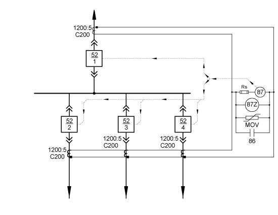
In the end, our high impedance differential scheme will look like the following diagram with:
- A stabilizing resistor (Rs) to force the false-differential currents through the CTs instead of the differential circuit
- A current detection unit (87) or voltage detection unit (87Z) set to trip if the differential current or voltage is greater than its setpoint
- An MOV to limit the possible voltage created across the differential circuit
- An 86 contact that will close after the relay trips to ensure no dangerous voltages are applied to the secondary circuit. It can also allow overcurrent functions inside the relay to operate other protective elements, such as breaker fail, if required
I hope you’ll read the next post in this series to learn more about high impedance busbar protection where we explain why 32V/0.016A would be terrible settings for this relay.
We will really dig into the math while looking at the following topics in the next high impedance differential scheme post:
- What size CT should you use?
- What happens inside the circuit during an external fault when one or more CTs saturate?
- What happens inside the circuit during an internal fault?
- What happens inside the circuit during an internal fault when one or more CTs saturate?
In the meantime, you can click the image below and we’ll send you a cheat sheet summary of this post you can take with you:
Did you like this post?
You can share it with these links:
Read More Articles:
Get and Manage Protective Relaying Online Training Courses for Your Entire Team

Can you comment on the functionality of a high impedance bus protection scheme with four breakers distributed between a closed bus tie breaker? Two breakers on each side of the closed bus tie?
You can use high impedance protection whenever the CTs are configured to monitor ALL of the current entering and leaving the system… as long as all of the CT rules are followed. The problem with a split bus system that has a tie breaker is accounting for all the different operating scenarios and making sure that no CT is shorted when transitioning from one scenario to another.
Dear Sir,
Thanks for your explanation.
I have a question. I wonder there is any reason any advantage in unit protection e.g., generator that use high impedance differential protection instead of low impedance prtection in modern and multi-function high-end class relays….
High impedance differential protection is optimized for locations with low impedance, high fault current, and a potential for additional inputs in the future; like a bus.
Generators, motors, and transformers have a high impedance, generators see relatively low fault currents, and all usually have fixed inputs; so they wouldn’t typically benefit from high impedance differential protection.