No products in the cart.
The Complete Guide to the Square Root of Three in Power Calculations
Zach Stone, P.E. contacted me after I (Chris Werstiuk writing right now) posted my recent “Understanding the Great Leading vs. Lagging Power Debate” post because I had incorrectly defined Apparent Power. Thanks to his keen eye and knowledge on the subject, no-one who purchased The Relay Testing Handbook: Generator Relay Protection Testing ever saw my mistake and I can still look like an expert 😃
After he called me out, I checked out his site and asked myself, “Where was this guy when I took the P.E. exam?” He graciously offered to write a guest post about the square root of three, which is probably the most common number used in relay testing that few people truly understand.
I hope you enjoy this guest post from Zach.
Chris Werstiuk
Have you ever wondered why the square root of three shows up in so many three-phase power calculations?
Where does this number come from, and why is it so special?
While the long answer to these questions comes from trigonometry, the good news is that we can use phasor diagrams to make explaining it very simple to understand.
Understanding phasor diagrams is an important skill for relay testing and working through the examples in this article will give you a much deeper understanding of and appreciation for the phasor quantities in phasor diagrams. Regardless of which part of the industry you work in, this will greatly benefit your career in electrical power and relay testing.
Since some of the math below may be unfamiliar to you, we’re going to work through it step by step with clear diagrams and explanations to make sure it is easy to follow along.
My name is Zach Stone, P.E., I am the lead instructor for the popular online study program for the NCEES® Electrical Power PE Exam at www.electricalpereview.com and in this article I’m going to help you discover why the square root of three shows up so often in three-phase power.
Let’s start by looking at the familiar wye connection of a power transformer.
1. The Wye Connection
Let’s pretend that we have three separate voltage meters connected across each line to neutral connection on each phase of the secondary terminals of a transformer that is wye connected:

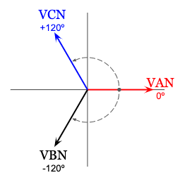
If we use a reference angle of zero degrees for the A-phase line to neutral voltage (VAN), the resulting voltage phasor diagram for a positive (ABC) sequence system would look like this:
Looking back at the transformer diagram, we can use the line to neutral voltage measurements to calculate the line voltage across the A-phase of the transformer (VAB) by summing the phasor quantities of the voltage in series from the A-phase terminal to the B-phase terminal:
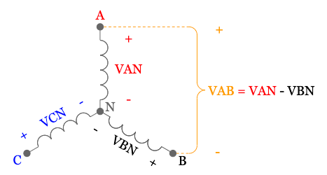
Let’s compare the positive voltage reference (+) at the A-phase terminal, and the negative voltage reference (-) at the B-phase terminal for the A-phase line voltage (VAB) to the A-phase and B-phase line to neutral voltages (VAN and VBN):
- The polarity of the A-phase line to neutral voltage (VAN) is in the same orientation as the polarity of the A-phase line voltage (VAB)
- The polarity of the B-phase line to neutral voltage (VBN) is in the opposite orientation of the polarity of the A-phase line voltage (VAB)
This is why the B-phase line to neutral voltage (VBN) is negative when we sum the voltage from the A-phase terminal to the B-phase terminal when we calculate the A-phase line voltage (VAB) using the formula:
VAB = VAN – VBN.
Remember that these are not regular numbers, they are phasor quantities with a magnitude and phase angle. In order to use phasor addition below, it will be easier to think of this formula as the addition of two phasors. Except one of them has been multiplied by negative like this:
VAB = VAN + (-VBN).
2. The Wye Connection – Multiplying a Phasor by Negative One
Multiplying a phasor (or vector) quantity by negative one is the same as rotating it by plus or minus 180 degrees on a phasor diagram with no change to the magnitude.
We can use this relationship to find -VBN from VBN:
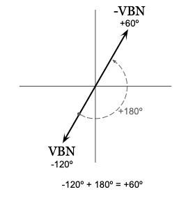
Since the B-phase line to neutral voltage (VBN) has a phase angle of negative 120 degrees, the phase angle for -VBN will be positive 60 degrees and equal in magnitude.
Since we will be adding VAN and -VBN to calculate the A-phase line voltage (VAB), let’s show just these two phasors on a phasor diagram:
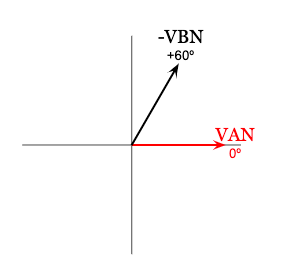
Now we are ready to use phasor addition to find the A-phase line voltage (VAB).
3. The Wye Connection – Phasor Addition
To add two phasors (or vectors) together, stack them on top of each other from head to tail then draw a new phasor starting from the origin and ending at the head of the last phasor.
Since we have two different phasors, we can do this two different ways and still result in the same phasor quantity for the A-phase line voltage (VAB):
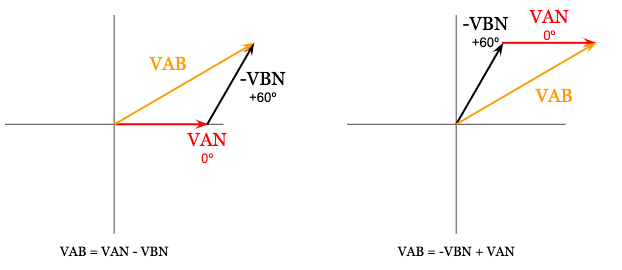
We’re going to arbitrarily use the first phasor addition diagram above on the left to calculate the A-phase line voltage (VAB), but either would result in the same final value.
We are also going to assume that the system is balanced, meaning that the magnitudes of each line to neutral voltage in every phase are equal. To simplify the coming math, we are also going to arbitrarily use a value of one volt for these values (VAN = VBN = VCN = 1V).
To calculate the A-phase line voltage (VAB) using phasor addition, we’re going to use a little bit of trigonometry but I promise it will be simple so don’t feel intimidated if you’re not too comfortable with the sine, cosine, and tangent functions.
First, we’ll calculate the real (a) and imaginary component (b) of -VBN, which is just another way of saying we’re going to calculate the length of the other two sides of the right triangle that -VBN makes with the horizontal axis:
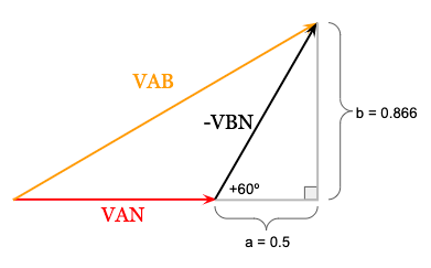
The real component (a) of -VBN is 0.5, which is found using the cosine function:
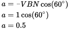
Remember that when we rotated VBN to find -VBN, the magnitude was not affected. This means that the magnitude of -VBN is still equal to one volt since we arbitrarily set the magnitudes of the line to neutral voltage for each phase to 1 volt earlier to simplify the math (VAN = VBN = VCN = 1V).
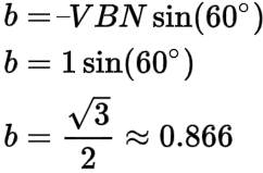
The imaginary component (b) of -VBN is approximately 0.866, which is found using the sine function:
We can use the real (a) and imaginary component (b) of -VBN, along with the magnitude of VAN = 1 volt at zero degrees to fill in the missing values for the phasor diagram for the A-phase line voltage (VAB):
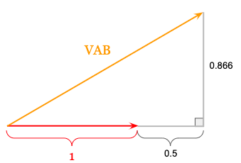
Notice in the figure above that the imaginary component of the A-phase line voltage (VAB) equals the imaginary component of -VBN (0.866).
To find the real component of the A-phase line voltage (VAB), we’ll just add the magnitude of VAN (1 volt) with the real component of -VBN (0.5) since they are both at the angle of zero degrees.
The real component of the A-phase line voltage (VAB) is 1 + 0.5 = 1.5:
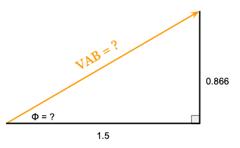
We’re now ready to finally calculate both the magnitude and phase angle of the A-phase line voltage (VAB) which is exactly where the square root of three comes from.
4. The Wye Connection – Calculating Line Voltage Magnitude and Phase Angle
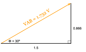
First, we’ll calculate the magnitude of the A-phase line voltage (VAB) using the Pythagorean Theorem where C is the Magnitude of VAB, A is the real component of VAB (1.5), and B is the imaginary component of VAB (0.866):
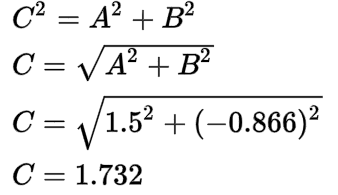
The magnitude of the A-phase line voltage (VAB) is 1.732 volts.
Next, we’ll calculate the phase angle of the A-phase line voltage (VAB) using tangent:
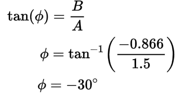
The phase angle (ɸ) of the A-phase line voltage (VAB) is 30 degrees.
The completed phasor diagram for the A-phase line voltage (VAB) looks like this:
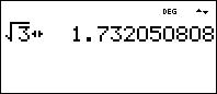
If you are familiar with three-phase power calculations, then the quantity of 1.732 should also be just as familiar.
Since we used a value of 1 volt for the magnitude of the A, B, and C-phase line to neutral voltages (VAN = VBN = VCN = 1V), the A-phase line voltage (VAB) is exactly 1.732 times larger than the A-phase line to neutral voltage (VAN).
1.732 is actually the square root of three:
5. The Wye Connection – Line vs Phase Relationships
The line voltage of a balanced three-phase system will always be greater than the line to neutral voltage by exactly the square root of three due to phasor addition.
In our case, we added the A-phase line to neutral voltage (VAN) with the negative B-phase line to neutral voltage (-VBN) to find the A-phase line voltage (VAB):
Since we used a reference angle of zero degrees for the A-phase line to neutral voltage (VAN), the A-phase line voltage (VAB) leads the A-phase line to neutral voltage (VAN) by exactly 30 degrees.
This same relationship of phasor addition is also why the line voltage will always lead line to neutral voltages by 30 degrees for a balanced and positive sequence (ABC) system.
If we were to complete this entire process for the other two remaining B and C phases and draw the resulting phasor diagram, we would see that this applies to every phase:
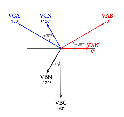
You’ll notice the phasor diagram above is the voltage phasor diagram for a balanced and positive sequence (ABC) wye connection that you are most likely already familiar with.
6. The Wye Connection – Using a Calculator
If you have a calculator that can handle vectors in both polar (magnitude and angle) and rectangular (real component and imaginary component) form, you can do all of the above in one single step in your calculator, although it really helps to know what the calculator is doing in the process so that you understand where these values come from.
Here is the same wye secondary transformer connection as before, with the A-phase Line Voltage (VAB) shown as the difference between the A-phase line to neutral voltage (VAN) and the B-phase line to neutral voltage (VBN):
Let’s calculate the A-phase line voltage (VAB) using a calculator.
I’m using the Texas Instruments 36X Pro (TI 36X Pro) which is my personal favorite for electrical calculations since it can handle vectors in both polar and rectangular form with ease.
We’ll use a value of 1V for the magnitude of the A-phase line to neutral voltage (VAN) and 1V for the magnitude of the B-phase line to neutral voltage (VAB) just like we did by hand.
We’ll also use 0 degrees for the A-phase line to neutral voltage (VAN) phase angle, and negative 120 degrees for the B-phase line to neutral voltage (VAB):
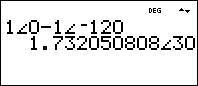
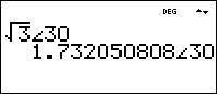
Notice that we get the same value of 1.732 for the magnitude of the A-phase line voltage (VAB) and 30 degrees for the phase angle of the A-phase line voltage (VAB).
Notice that this is identical to a magnitude of the square root of three at an angle of 30 degrees:
7. The Delta Connection
Now that we understand where the square root of three comes from for wye connections, what about delta connections?
Let’s look at the secondary terminals of a transformer that is delta connected and show the phase currents inside of the delta connection:
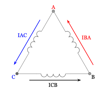
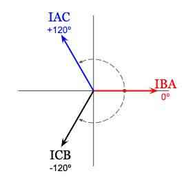
Using an ammeter in each phase, and a reference angle of zero degrees for the phase current in the A-phase of the delta connection (IBA), the resulting phasor diagram of the delta phase currents would look like this:
Looking back at the transformer diagram, we can calculate the A-phase line current leaving the delta connected secondary of the transformer using Kirchoff’s Current Law:
Kirchoff’s Current Law states that the sum of the current entering a node must equal the sum of the current leaving the same node.
Looking at the A-phase terminal above, notice that the only current entering is the A-phase delta phase current (IBA), while the current leaving the node is the C-phase delta phase current (IAC) and the A-phase line current (IA).
We’ll use Kirchoff’s Current Law to set these equal to each other then re-arrange to solve for the A-phase line current (IA):

The A-line current (IA) leaving the delta connected transformer secondary is equal to the difference of the A-phase delta phase current (IBA) and the C-phase delta phase current (IAC).
Or, if we want to think in terms of addition instead, The A-line current (IA) leaving the delta connected transformer secondary is equal to the sum of the A-phase delta phase current (IBA) and negative one times the C-phase delta phase current (IAC).
Look familiar? This is very similar to the relationship that we worked with for the previous example of the A-line voltage for the wye connection.
8. The Delta Connection – Multiplying a Phasor by Negative One
Just like before, first we’ll find -ICA by rotating ICA by plus or minus 180 degrees:
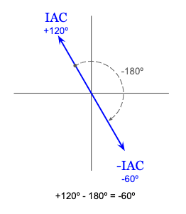
Since the C-phase delta phase current (IAC) has a phase angle of 120 degrees, the phase angle for negative IAC will be negative 60 degrees. Remember that this has no effect on the magnitude.
Since IA = IBA – ICA, let’s show just IBA and -ICA on a phasor diagram:
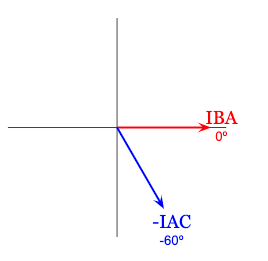
Just like before, we’re ready to use phasor addition by stacking each phasor on top of the other and drawing the resulting phasor from the origin.
9. The Delta Connection – Phasor Addition
Since we are adding two phasors, we carry out phasor addition two different ways and still result in the same phasor quantity for the A-phase line current (IA):
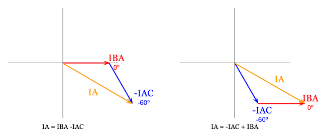
We’re going to arbitrarily pick the first phasor addition diagram above on the left to calculate the A-phase line current (IA).
Just like before, we are also going to assume that the system is balanced, meaning that the magnitude of the delta phase current in every phase is equal. To simplify the coming math, we are also going to arbitrarily use a value of one amp for these values (IBA = ICB = IAC = 1A).
To calculate IA, we’re going to use the same trigonometry relationships as before.
First, we’ll calculate the real (a) and imaginary component (b) of -IAC, which is just another way of saying we’re going to calculate the length of the other two sides of the triangle that -IAC makes with the horizontal axis:
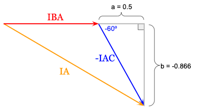
The real component (a) of -IAC is 0.5, which is found using cosine:
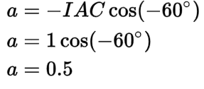
Remember that when we rotated IAC to find -IAC, the magnitude was not affected. This means that the magnitude of -IAC is still equal to one amp since we arbitrarily set the magnitudes of the delta phase current in each phase to 1 amp to simplify the math (IBA = ICB = IAC = 1A).
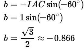
The imaginary component (b) of -IAC is approximately -0.866, which is found using sine:
We can use the real (a) and imaginary component (b) of -IAC, along with the magnitude of IBA = 1 amp at zero degrees to fill in the values for the phasor diagram for the A-phase line current (IA):
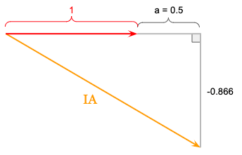
Notice that the imaginary component of the A-phase line current (IA) equals the imaginary component of -IAC (0.866).
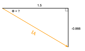
To find the real component of the A-phase line current (IA), we’ll just add the magnitude of IBA (1 amp) with the real component of -IAC (0.5) since they are both at the same angle of zero degrees.
The real component of the A-phase line current (IA) is 1 + 0.5 = 1.5:
We’re now ready to finally calculate both the magnitude and phase angle of the A-phase line current (IA) which is exactly where the square root of three comes from.
10. The Delta Connection – Calculating Line Voltage Magnitude and Phase Angle
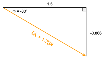
First, we’ll calculate the magnitude of the A-phase line current (IA) using the Pythagorean Theorem where C is the Magnitude of IA, A is the real component of IA (1.5), and B is the imaginary component of IA (-0.866):
The magnitude of the A-phase line current (IA) is 1.732 amps.
Next, we’ll calculate the phase angle of the A-phase line current (IA) using tangent:
The phase angle (ɸ) of the A-phase line current (IA) is negative 30 degrees.
The completed phasor diagram for the A-phase line current (IA) looks like this:
Again, if you are familiar with three-phase power calculations, then the quantity of 1.732 should also be just as familiar.
Since we used a value of 1 amp for the magnitude of the A, B, and C-phase delta phase currents (IBA = ICB = IAC = 1A), the A-phase line current (IA) is exactly 1.732 times larger than the A-phase delta phase current (IBA).
1.732 is actually the square root of three:
11. The Delta Connection – Line vs Phase Relationships
The line current of a balanced three-phase system will always be greater than the delta phase current by exactly the square root of three due to phasor addition.
In our case, we added the A-phase delta phase current (IBA) with the negative C-phase delta phase current (-IAC) to find the A-phase line current (IA):
Since we used a reference angle of zero degrees for the A-phase delta phase current (IBA), the A-phase line current (IA) lags the A-phase delta phase current (IBA) by exactly 30 degrees.
This same relationship of phasor addition is also why the line current of the system will always lag the delta phase current by 30 degrees for a balanced and positive sequence (ABC) system.
If we were to complete this entire process for the other two remaining B and C phases and draw the resulting phasor diagram, we would see that this applies to every phase:
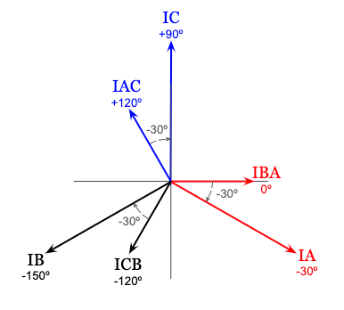
You’ll notice the phasor diagram above is the current phasor diagram for a balanced and positive sequence (ABC) delta connection that you are most likely already familiar with.
12. The Delta Connection – Using a Calculator
Just like before, let’s use the TI 36X Pro to calculate the A-phase line current (IA) leaving the delta connection and compare it to the value we got by hand.
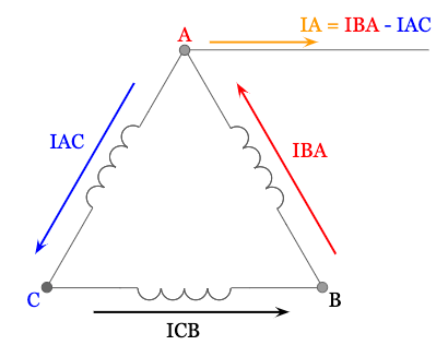
Here is the same delta secondary transformer connection, with the A-phase Line current (IA) shown as the difference between the A-phase delta phase current (IBA) and the C-phase delta phase current (IAC):
We’ll use a value of 1A for the magnitude of the A-phase delta phase current (IBA) and 1A for the magnitude of the C-phase delta phase current (IAC) just like we did by hand.
We’ll also use 0 degrees for the A-phase delta phase current (IBA) phase angle, and positive 120 degrees for the C-phase delta phase current (IAC):
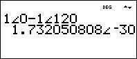
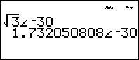
Notice that we get the same value of 1.732 for the magnitude of the A-Phase line current (IA) and negative 30 degrees for the phase angle of the A-phase line current (IA).
Notice that this is identical to a magnitude of the square root of three at an angle of negative 30 degrees:
13. Three-phase Apparent Power and the Square Root of Three
We explored where the square root of three comes from for both wye and delta connections, but what about the square root of three in the three-phase apparent power formula?
The three-phase apparent power formula is the product of the square root of three, line voltage magnitude (VL), and line current magnitude (IL):

These values are magnitudes only, so avoid the common mistake of using phasor quantities in this formula to calculate both apparent power and the power angle.
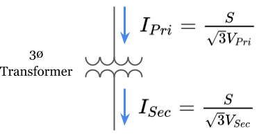
This formula is most commonly used to calculate the full load amps of a power transformer by plugging in the three-phase apparent power rating of a transformer [volt-amps], and either the line voltage of the primary connection to calculate the primary full load amps drawn by the transformer, or the line voltage of the secondary connection to calculate the secondary full load amps delivered by the transformer:
To see where the square root of three comes from in this formula, let’s start by showing how it is derived from single-phase apparent power (S1ø).
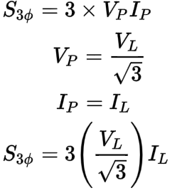
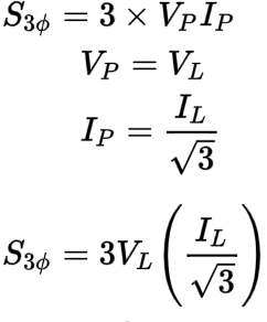
For a balanced three-phase system, the amount of apparent power in each phase is always equal. This means that three-phase apparent power (S3ø) is really just three times the amount of apparent power in any one given phase (S1ø) of a balanced three-phase system:

The single-phase apparent power (S1ø) in any one given phase of a balanced three-phase system is the product of the magnitude of the phase voltage (VP) and the magnitude of the phase current (IP):

Let’s plug this back into the three-phase apparent power (S3ø) formula:

Coming up, let’s use this version of the three-phase apparent power formula (S3ø) and see how it applies to a wye or delta connection to discover where the square root of three in the original formula comes from.
Let’s start with a wye connection first.
14. The Wye Connection, Three-phase Apparent Power, and the Square Root of Three
For a wye connection, the magnitude of the line to neutral phase voltage (VP) is smaller than the magnitude of the system line voltage (VL) by a factor of the square root of three as we found in the first half of this article.
The magnitude of the phase current (IP) of a wye connection, however, is equal to the magnitude of the line current (IL) of the system.
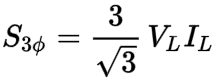
When we plug in the wye phase voltage and phase current relationships into the three-phase apparent power (S3ø) formula, it changes to look like this:
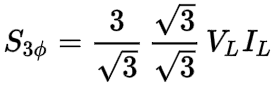
We can start simplifying by separating the coefficients (3 and 1/√3) away from the variables (VL and IL):

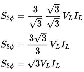
Next, here comes the tricky part. We are going to multiply by the square root of three over the square root of three (√3/√3). Since this is the same as multiplying by 1, it does not change the value of the formula (any number multiplied by 1, is the same number that it was before):
Now, the two square root of threes on the bottom of each fraction when multiplied together will equal three (√3 X √3 = 3):
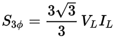
Last, the three on top of the fraction and the three on the bottom of the fraction will cancel (3/3 = 1):
The result is the three-phase apparent power (S3ø) formula that we are familiar with that includes the square root of three.
The square root of three in this formula comes from plugging in the wye phase voltage and phase current relationships into the three-phase apparent power (S3ø) formula.
Does the same hold true for a delta connection?
15. The Delta Connection, Three-phase Apparent Power, and the Square Root of Three
For a delta connection, the magnitude of the phase current (IP) is smaller than the magnitude of the system line current (IL) by a factor of the square root of three as we found in the first half of this article.
The magnitude of the phase voltage (VP) of a delta connection, however, is equal to the magnitude of the line voltage (VL) of the system.
When we plug in the delta phase current and phase voltage relationships into the three-phase apparent power (S3ø) formula, it changes to look like this:
Again, we can start simplifying by separating the coefficients (3 and 1/√3) away from the variables (VL and IL):
Let’s multiply again by the square root of three over the square root of three (√3/√3) since this is the same as multiplying by 1, then continue to simplify the expression using the same techniques as before:
The result is again, the same three-phase apparent power formula that we are familiar with that includes the square root of three. The square root of three in this formula comes from plugging in the delta phase voltage and phase current relationships into the three-phase apparent power (S3ø) formula.
Notice that the square root of three in the three-phase apparent power (S3ø) formula exists regardless if a delta or wye connection is present as long as we use the line values of the system. Neat!
16. Who I am and Where You Can Find Me
I hope you enjoyed exploring where the square root of three comes from in most three-phase electrical power calculations.
My name is Zach Stone, P.E. and I am the lead instructor for the popular online study program for the NCEES® Electrical Power PE Exam at www.electricalpereview.com. I create all of their educational material and host their live classes every semester.

Zach Stone, P.E.
Electrical PE Review, INC
Here’s my 10-second bio:
- I’m a professionally licensed engineer in the state of Florida.
- I earned my ABET-accredited electrical engineering degree in 2010.
- I passed both the FE and PE exam on the first try.
- I have rich industry experience in industrial automation, motor control, power generation, and medium voltage substations.
- I enjoy the math behind electrical engineering and teaching others.
If you’re an electrical engineer that is planning on taking the PE exam sometime in the future, or if you’d like to read more articles on the nuances of the math behind electrical engineering, you can find me at www.electricalpereview.com.
If you truly want to learn something, it is a good idea to see how different people describe a topic. I briefly cover this topic in The Relay Testing Handbook: Principles and Practice / Chapter 1 section D) Three-Phase Connections [page 14 and 15]. You can review if you want to compare the two different explanations to dig deep and truly understand where the square root of three comes from.
We’re always looking for different perspectives here at RelayTraining.com. Contact us at [email protected] if you want to submit a guest post about a relay testing topic.
Chris Werstiuk
Did you like this post?
You can share it with these links:
Read More Articles:
How to Test Overcurrent Relays: An Introduction to Protective Relaying Online Seminar - Final 2022 Update
Great. i will like to be in touch.
Nice brief refresher to remind me of what I learned years ago. I enjoyed the teaching technique…EASY to follow!
Very enlightening script.
👍️ i will like to be in touch.
Hi Zach,
Its great and outstanding information. I like the way you explain and implement the math theories to solve the electrical engineering problems analysis and understanding. Excellent job.
excellent Presentation