No products in the cart.
Methods of Clearing Ground Faults from Silent Sentinels 1924
Silent Sentinels 1924 Excerpt #5
This excerpt from the 1924 version of Silent Sentinels discusses how electrical engineers understood how alternating-current systems (AC) operated in 1924. This is the 5th in the series. Follow these links to learn more about this series and the 1924 version of Silent Sentinels. We also cover this subject in The Relay Testing Handbook: Principles and Practice.
3 – Methods of Clearing Ground Faults
Solidly and Low-Resistance-Grounded Neutral Systems
These systems when protected by types CO, CR and CD relays require no additional relays for wire-to-ground faults. Three current transformers and three relays are necessary for the complete protection of each circuit-breaker.
However, where type CZ impedance relays arc used in order to obtain the minimum time for clearing faults, two sets of impedance elements are required for phase-to-phase and phase-to-ground faults. The reason for this is that a ground fault on one wire results in 57.7 per cent. voltage being maintained across two sides of the voltage triangle, and 100 per cent. voltage across the third side. The voltage between the grounded wire and neutral is of course zero, or nearly so. If only three elements, having their directional element potential coils connected in star, are used, a wire-to-wire short circuit will reduce the voltage across each relay coil from 57.7 per cent. of line voltage to 28.8 per cent. line voltage, so that each relay still has 50 per cent. normal voltage impressed across it. With 50 per cent. normal voltage acting on the potential coil of the CZ relay the time required to close the contacts is entirely too long for satisfactory operation, and 2 sets of elements must be employed for complete protection.
Medium-Resistance-Grounded Neutral System
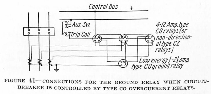
Relay equipment additional to that required for line short circuits is required to care for phase-to-ground failures. For those installations, where the magnitude of the ground current in the circuit and the ratios of the current transformers are such as to produce a single-phase current of at least 2 amperes in the secondary of one current transformer for a fault from that wire to ground, a type CO relay having a low-current winding is inserted in the neutral connection between the neutral point of the line relays and the neutral point of the current transformer secondaries. The low-current type CO relay has taps for operation at 0.5, 0.6, 0.8, 1.0, 1.5, 2.0, and 2.5 amperes. It can generally be operated on the 0.5-ampere tap without danger of tripping improperly, as under normal operation there is no current flowing in the neutral connection.
Fig. 41 shows the connections for the ground relay when the circuit-breaker is controlled by type CO overcurrent relays. It will be observed that the tripping contacts of the ground relay parallel the tripping contacts of the line relays. The same scheme of current and tripping connections is employed when non-directional single-impedance element type CZ impedance relays are used to protect the feeder against line faults.
When the circuit-breaker is controlled by type CR directional overcurrent or type CZ single-impedance element relays for phase-to-phase faults, the low-current relay is inserted in the neutral circuit for ground fault protection. The tripping contacts do not, however, go directly to the circuit-breaker trip coil, but are connected in series with the directional contacts of the line relays, to secure proper directional indication on ground faults as well as line faults. A tap must therefore be provided on the line relays between the directional element contacts and the overcurrent or impedance element contacts. Fig. 42 shows the connections using three type CR line relays and one type CO low energy ground relay. The same tripping circuit connections hold when type CZ impedance relays are used for line faults.
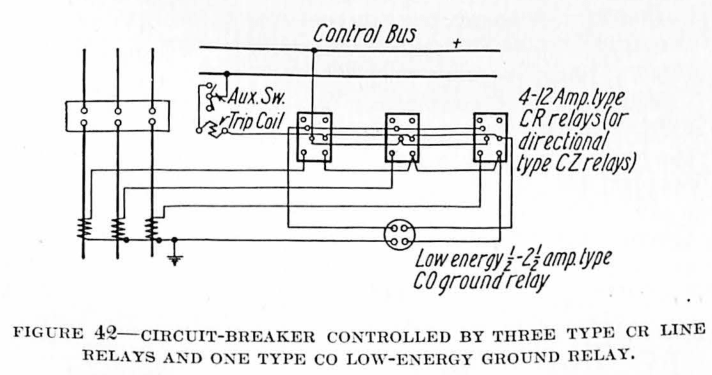
This arrangement should be used with care. It has been found that a high resistance at the point where an accidental ground occurs will limit the current to such a small value that the load current flowing through the CR relays will be greater than the ground current, and the CR relays will not operate in the proper direction.
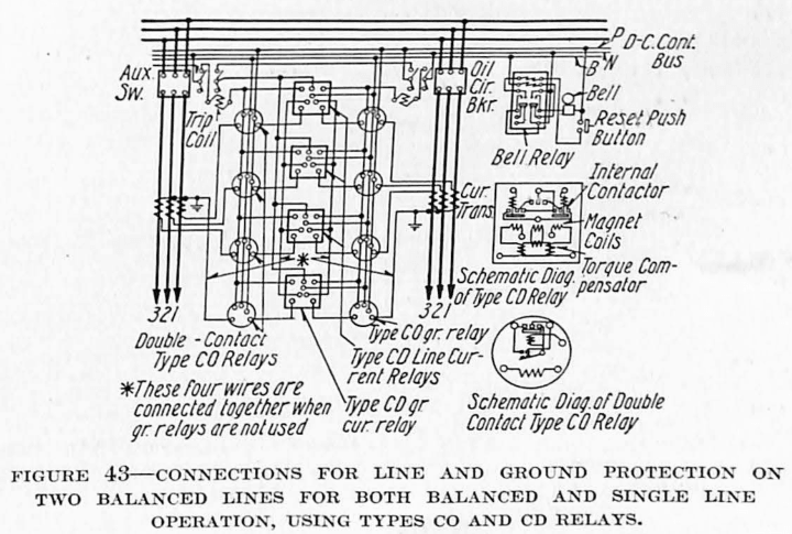
A low-current type CD selective differential current relay is available for ground protection at those locations protected against line faults by type CD relays. Each winding is provided with taps for 0.5, 0.6, 1.2 and 2.0 amperes operating current. One winding is connected in each neutral connection of the balanced pair of lines. Fig. 43 shows the complete connections for line and ground protection on two balanced lines for both balanced and single-line operation.
High-Resistance-Grounded Neutral System
Protection against wire-to-ground faults on high-resistance-grounded neutral systems cannot readily be provided unless the magnitude of the ground current in the circuit and the ratio of the current transformers are such as to produce 1 1/2 or 2 amperes in the secondary of one current transformer with a ground fault on that wire. Since the ground current is less than the load current in the circuit to be protected, a directional element which shall be independent of load is required.
Fig. 44 shows complete line and ground protection for two parallel lines on a high-resistance-grounded neutral system.
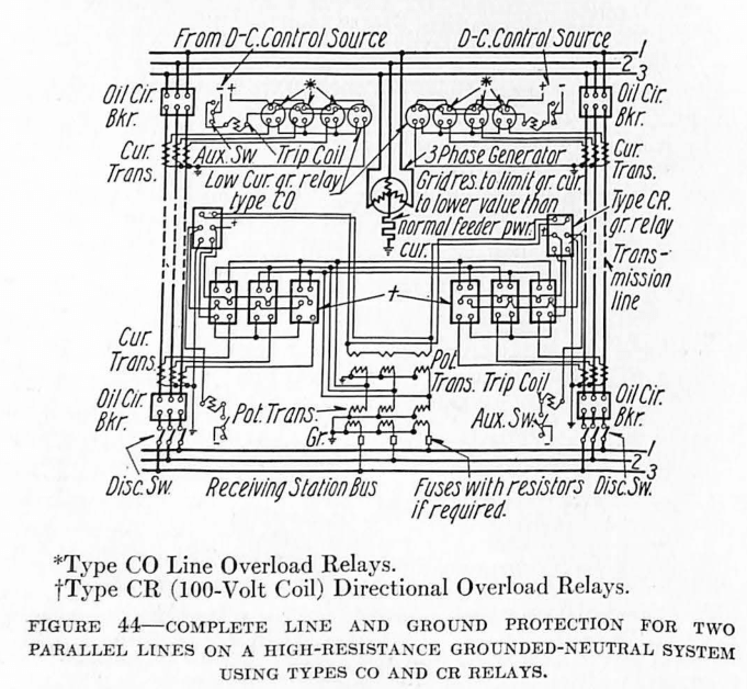
The line potential transformers are connected star-star, with the star points grounded. The line relay potential coils are energized by the delta voltages of this bank. If the potential transformers are so chosen as to give 115 volts single-phase secondary when energized by a single-phase voltage of line-to-line value, the line relays should be provided with 125-volt potential coils. The secondaries of the line potential transformers also energize an auxiliary bank of three 200/100-volt potential transformers connected star on the primary side, the star point being connected to the two star points of the line potential transformers. The secondaries of the auxiliary bank of transformers form a closed delta through the potential coil of the ground relay.
A low-current low-energy directional type CR relay, having the same current winding as the low-current type CO previously mentioned, is required for ground protection. The current coil of this relay is connected between the neutral point of the current transformer secondaries and the neutral point of the line relays.
When a fault from one wire to ground occurs, the distortion of the voltage triangle caused by current being fed to the ground fault by the potential transformer develops sufficient voltage across the potential coil of the directional relay to obtain, in conjunction with the residual current in the relay, the proper directional indication. The proper time of operation for the relay is secured by adjustment of the time index lever of the overcurrent element.
When power transformer banks are connected star-delta and the star point is grounded through a resistor the potential for the directional ground relays can be secured by connecting the primary of a 200/ 100-volt potential transformer between ground and a point on the resistor which is 200 volts above ground when carrying the maximum ground current. The secondary of the potential transformer energizes the potential coil of the relay.
Did you like this post?
You can share it with these links:
Read More Articles:
Please Explain the Principle of Weak InFeed Echo Permissive Over Reach Transfer Trip Schemes?